Non-Overhaul Removal and Replacement
Teledyne Continental Motors, Inc.
TM
10-14
IOF-550 Permold Series Engine Maintenance Manual
1 April 2007
10-4.
Alternator Replacement
Replace the alternator if it fails to deliver the correct voltage and amperage to the aircraft
electrical system. Table 10-8 lists the reference documents for various alternators
available for the IOF-550 Permold Series engines.
Table 10-8.
Alternator Document Chart
Alternator Document
12 Volt, 70 amp
Kelly Aerospace Power Systems Alternator Overhaul Manual OE-A2
24 Volt, 60 amp
TCM’s Alternator Service Instructions (X30531-3)
24 Volt, 60 amp
Kelly Aerospace Power Systems Lightweight Series Alternator
Maintenance Manual (ES1010-1)
24 Volt, 70 amp
Kelly Aerospace Power Systems Lightweight Series Alternator
Maintenance Manual (ES1010-2)
24 Volt, 100 amp
TCM’s Alternator Service Instructions (X30531-3)
24 Volt, 100 amp
Kelly Aerospace Power Systems Lightweight Series Gear Driven
Alternator Maintenance Manual (ES1011)
10-4.1. Direct Drive Alternator Removal
WARNING
If all power is not disconnected, a loose or broken wire could
allow the engine to start and the propeller to rotate. Do not
stand or place equipment within the arc of the propeller.
Procedure
1.
Disconnect electrical power to the engine; turn the Ignition Switch OFF.
2.
Disconnect the aircraft battery in accordance with the aircraft manufacturer’s
instructions.
3.
Disconnect electrical connections from the alternator.
4.
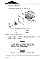
Remove the plain washer (8), lock washer (9), and nut (10) from the four alternator
mounting studs; discard the lock washers (8).
5.
Remove the alternator from the mounting studs.
6.
Remove and discard the gasket (1) from the mounting studs.
7.
Alternator disassembly requires specific test equipment. Refer to Table 10-8 to select
the appropriate instructions for further alternator disassembly.
8.
Inspect the drive hub according to the “Drive Hub Slippage Inspection” in Chapter 7.
10-4.1.1. Alternator Drive Hub Removal
Procedure
1.
Remove the alternator from the crankcase (Section 10-4.1, Direct Drive Alternator
Removal)
2.
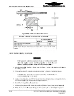
Remove the cotter pin (7) and slotted nut (4).
3.
Pull the drive hub assembly (5) from the alternator shaft.


