Teledyne Continental Motors, Inc.
TM
Engine
Description
IOF-550 Permold Series Engine Maintenance Manual
2-19
1 April 2007
2-2.5.2. Engine Low Voltage Harness
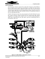
The Engine Low Voltage Harness connects essential components of the FADEC System.
This harness acts as a signal transfer bus interconnecting the Electronic Control Units
(ECUs) with aircraft power sources, the Ignition Switch, Speed Sensor Assembly (SSA),
Health Status Annunciator (HSA), temperature and pressure sensors. The fuel injector
coils and all sensors, except the SSA, Fuel Pressure and Manifold Pressure Sensors, are
hardwired to the low voltage harness.
The Engine Low Voltage Harness attaches to the cabin harness through firewall-mounted
bulkhead connectors. Engine status is conveyed from the ECUs to the instrument panel
through the cabin harness bulkhead connector assembly.
2-2.5.3. High Voltage Harness
Each high voltage harness lead connects a spark plug to the Electronic Control Unit spark
towers. The spark tower pair is connected to opposite ends of one of the coil packs
located in the upper portion of the ECU. Each coil pack generates high voltage pulses for
two spark plug towers. One tower emits a positive polarity pulse while the other tower
emits a negative polarity pulse.
The control channel within each ECU commands the two coil packs to control the
ignition spark for two engine cylinders. The FADEC System employs a waste spark
ignition system, igniting each cylinder’s spark plugs twice per engine cycle - once on the
compression stroke and again on the exhaust stroke. The ECU emits a high voltage pulse
through the high voltage harness to fire the top spark plug on the compression stroke and
the bottom spark plug on the exhaust stroke for the opposite cylinder.
Ignition spark is mechanically synchronized with the engine’s crankshaft position and
retarded and advanced throughout the engine’s operating range by the ECU, dependent
upon engine load conditions. The spark energy is also varied with respect to engine load.
2-2.5.4. Aircraft Boost Pump Mode Switch
The FADEC system integrates with the airframe boost pump mode switch (BPMS) to
command the airframe boost pump to increase fuel pressure when the fuel pressure
sensors detect the pressure is insufficient for proper operation.
On the IOF-550-B and C, with the BPMS in AUTO position and the ignition switch in L
or BOTH, FADEC will command the boost pump to maintain fuel supply pressure at 25
psi available at the distribution block. The IOF-550-N, P, and R will command the boost
pump to ON whenever the ignition is enabled and engine RPM is less than 1500 RPM.
2-2.5.5. Best Power /Best Economy Switch
The optional best power/best economy switch replaces the conventional engine function
of mixture leaning. At cruise altitude, the pilot may select either Best Power or Best
Economy mode of operation. A two position switch on the instrument panel allows the
pilot to override the cruise fuel mixture selected by the FADEC computers.
The switch applies a ground signal to the FADEC system in Best Economy mode. In Best
Power mode the switch removes the ground from the FADEC system. This arrangement


