Teledyne Continental Motors, Inc.
TM
Troubleshooting
8-14.
FADEC Schematics
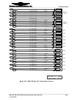
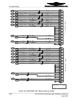
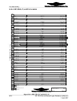
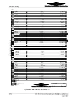
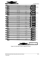
The following schematics will aid in FADEC troubleshooting. Wiring harnesses differ
significantly between engine models. Refer to the appropriate schematics for the subject
engine.
NOTE: Please note the numbers enclosed in circles in the
schematics indicate the page the signal resumes on.
34 35 36 37 38 39 40 41 42 43 44 45 46 47 48 49 50
1
2
3
4
5
6
7
8
9
10 11 12 13 14 15 16 17
18 19 20 21 22 23 24 25 26 27 28 29 30 31 32 33
Figure 8-5.
50-pin connectors
1
2
3
4
5
6
7
8
9
10 11 12 13
14 15 16 17 18 19 20 21 22 23 24 25
Figure 8-6.
25-pin connectors
Figure 8-7.
6-pin connectors
IOF-550 Permold Series Engine Maintenance Manual
8-41
1 April 2007


