Non-Overhaul Removal and Replacement
Teledyne Continental Motors, Inc.
TM
10-54
IOF-550 Permold Series Engine Maintenance Manual
1 April 2007
3.
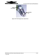
Slide the compression fitting nut onto the sensor body followed by the ferrule.
4.
Insert the MAT Sensor into the compression fitting. Thread the nut onto the fitting
until finger tight. Adjust the probe depth so the mark made in step 2 is visible at the
outboard edge of the nut.
5.
While holding the MAT Sensor body in position, torque the compression fitting nut to
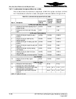
Appendix B specifications.
6.
Splice the new sensor into the engine low voltage harness according to instructions in
Section 10-5.2, “Non-EGT Sensor and Lead Wire Replacement.”
7.
For proper operation of the engine, route, clamp, support, and protect the wires in the
engine low voltage harness in a manner to prevent chafing, fretting, and wear of the
lead wires. Route and secure the harness according to Appendix C, “Harness
Routing” Instructions.
8.
Perform a “FADEC Level I Diagnostics” in Chapter 8, Troubleshooting of this
manual to check the FADEC System. If the FADEC System fails this diagnostic
check, troubleshoot the system until the malfunction is corrected.
9.
Perform an “Engine Operational Check” according to the instructions in Chapter 6,
Operational Performance Checks.
10-6.19. Exhaust Gas Temperature Sensor Removal
Procedure
1.
Locate the EGT sensor to be removed.
2.
Cut the EGT sensor lead wires as close as practical to the sensor body. Note the
length of removed wire for reference during sensor replacement.
3.
Loosen the band clamp securing the sensor completely. Spread the clamp to allow
removal of the sensor from the exhaust manifold.
4.
Remove and discard the EGT sensor.
5.
Clean the sensor mounting location in the exhaust manifold with a small wire brush.
6.
Instructions to prepare the new sensor leads are included in Section 10-5.1, “EGT
Sensor and Lead Wire Replacement.”
10-6.20. Exhaust Gas Temperature Sensor Installation
The exhaust gas temperature (EGT) sensors are designated for location by a label (at the
base of the sensor) for each cylinder. These sensors are “hardwired” into the engine low
voltage harness.
Each sensor is fitted with adjustable, worm style band clamps for easy installation. To
install the EGT sensors, perform the following procedure:
CAUTION: Route engine wiring to avoid contact with sharp edges
or extreme heat. Chafing or burned wires will result in faulty
indications and possible engine failure.
Procedure


