Maintenance Inspections
Teledyne Continental Motors, Inc.
TM
7-26
IOF-550 Permold Series Engine Maintenance Manual
1 April 2007
3.
Position the piston at bottom dead center on the power stroke. The exhaust valve will
be open with the piston in this position.
4.
Insert the borescope probe through the upper spark plug hole and inspect the internal
surfaces of each cylinder, including the exhaust valve and exhaust valve seat. Use
Table 7-5, "Borescope Inspection Objectives and Corrective Actions” guidelines.
5.
Position the piston at bottom dead center at the end of the intake stroke.
6.
Insert the borescope through the upper spark plug hole and inspect the intake valve
and valve seat. Use Table 7-5 to interpret findings.
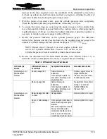
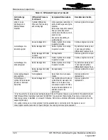
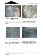
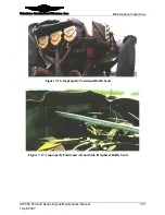
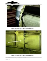
Figure 7-8 through Figure 7-14 provide guidance during borescope examinations.
Table 7-5.
Borescope Inspection Objectives and Corrective Actions
Item
Objective
If Abnormality Noted
Combustion
Chamber
Inspect:
Valve seat inserts for erosion, burning
Sparkplug heli-coils for protrusion into combustion
chamber
Heavy carbon deposits/presence of excessive oil
Remove cylinder for repair.
Exhaust
Valve Face
Inspect for signs of leakage or damage indicated by:
•
Localized discoloration on the valve face
circumference (Figure 7-9)
•
Minute cracks
•
Erosion (missing material)
Repair or replace cylinder.
Intake Valve
Face
Inspect for signs of leakage or damage indicated by:
•
Localized discoloration on the valve face
circumference
•
Erosion (missing material)
Repair or replace cylinder.
Inspect exposed surface of bore for:
•
Heavy scoring/piston rub (Figure 7-12)
•
Piston pin rub (wide band pattern in horizontal
plane at 3 o’clock and/or 9 o’clock position)
1
Repair or replace cylinder
•
Corrosion (Figure 7-11)
Excessive oil in cylinder/heavy deposits of carbon in
combustion chamber
Remove cylinder for repair
Cylinder Bore
Upper portion of cylinder bore has no visible hone
pattern (Figure 7-13 and Figure 7-14)
Normal indication for in service
cylinders
Piston Head
Inspect for:
•
Piston crown for erosion, missing material
•
Visible damage from foreign debris
Remove cylinder for repair
1
Remove cylinder for repair or replacement. Perform complete inspection of connecting rod bushing for
correct installation and finishing.


