Engine Description
Teledyne Continental Motors, Inc.
TM
2-26
IOF-550 Permold Series Engine Maintenance Manual
1 April 2007
2-2.6.2. Fuel Injector Nozzles
Three Electronic Control Units (ECU) meter the fuel to individual cylinders. The ECU
monitors changes in air density and engine speed to determine how much fuel will be
injected into the intake port of the cylinder.
The fuel distribution block distributes fuel to each of the fuel injector nozzles. ECUs
constantly monitored the fuel pressure using dual redundant fuel pressure sensors
mounted on the fuel distribution block.
The FADEC System controls the fuel supplied to each cylinder using solenoid-actuated
sequential port fuel injectors. A fuel injector assembly is located in each cylinder head,
one fuel injector per cylinder. The fuel injector is threaded on both ends; outlet screws
into the tapped fuel injector boss in the cylinder head.
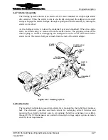
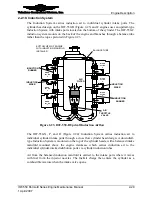
The fuel injector assembly is made up of two parts: the control coil and the injector
nozzle (Figure 2-20). The internal components of the fuel injector nozzle consist of a
pintle valve and a spring. The solenoid creates an electromagnetic field to lift the pintle
valve and open the path for fuel to flow. The solenoid coil fits over the pintle valve body
and is held in place with a jam nut that threads onto the valve body. When electrical
current ceases to flow through the solenoid, the spring force closes the pintle valve and
shuts off the fuel flow to the fuel injector. The valve design and injector end form a self-
atomizing feed.
WASHER
INJECTOR BODY
SOLENOID COIL
LEAD WIRE
FUEL LINE
RETAINING NUT
TIE STRAP
SUPPORT
WASHER
INJECTOR BODY
SOLENOID COIL
LEAD WIRE
FUEL LINE
RETAINING NUT
TIE STRAP
SUPPORT
Figure 2-20.
FADEC Fuel Injector and Solenoid


