Teledyne Continental Motors, Inc.
TM
Non-Overhaul Removal and Replacement
IOF-550 Permold Series Engine Maintenance Manual
10-65
1 April 2007
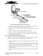
Figure 10-55.
Oil Pump and Oil Pressure Relief Valve
12.
Assemble the plunger, spring, and seat of the oil pressure relief valve (Figure 10-55)
and slide it into the oil pump housing pressure relief valve cavity.
13.
Ensure that relief valve components are aligned and install them in the oil pump
housing.
14.
Torque the housing fasteners according to Appendix B instructions.
15.
Safety wire the relief valve housing in accordance with instructions in Appendix C.
16.
Adjust the engine oil pressure during the “Engine Operational Check” in Chapter 6,
Operational Performance Checks.
10-7.5.1. Reface the Oil Pressure Relief Valve Seat
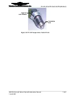
Reface the valve seat when it is nicked, gouged or rough using the Oil Pressure Relief
Spot Facer Tool (Figure 10-56) by performing the following procedure:
Procedure
1.
Using only light finger pressure, turn the Oil Pressure Relief Spot Facer Tool on the
valve seat.
2.
After refacing the valve seat, verify that the depth from the top of the oil pump
housing to the valve seat face does not exceed the specified limit in 10-7.7. Oil pump
housings exceeding specified limits must be discarded and replaced.
3.
Thoroughly clean the oil pressure relief valve cavity to remove all debris from the
refacing procedure.
4.
Perform the “Engine Operational Check” in Chapter 6, Operational Performance
Checks


