Teledyne Continental Motors, Inc.
TM
Non-Overhaul Removal and Replacement
IOF-550 Permold Series Engine Maintenance Manual
10-95
1 April 2007
10-8.11. Hydraulic Tappet Removal
Procedure
1.
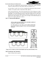
Remove the Valve Train and Pushrods according to instructions in Section 10-8.1 or
10-8.3.
2.
Position the crankshaft so the valves of the cylinder being worked on are fully closed.
3.
Remove the hydraulic tappets from the crankcase bores.
a.
Identify the location from which the tappets are removed, they must be re-
installed (if acceptable) in the same location.
b.
Inspect the hydraulic tappets, lifter bores and cam lobes for nicks, scratches,
gouging, spalling or galling using the guidance in Chapter 7. Replace hydraulic
tappets which exhibit face or body wear exceeding 10% of the surface area. If
hydraulic tappets require replacement, inspect the cam lobes of the associated
valve for abnormal wear.
4.
Inspect the hydraulic tappet retaining rings and pushrod cups. If the spring is
collapsed or the spring will not compress, replace the hydraulic tappet. Replace
hydraulic tappets which exhibit faulty retaining rings, damaged pushrod cups, or
appear to have collapsed or stuck spring mechanisms.
10-8.12. Hydraulic Tappet Installation
Procedure
1.
Perform the dimensional inspection listed in Section 10-8.5, “Cylinder Service
Limits” that apply to the hydraulic tappets (lifters) and pushrod tubes. Replace parts
which fail to meet the service limits.
2.
Gather the replacement parts necessary to satisfy the 100% replacement criteria in
Appendix C.
3.
Lubricate all tappet faces using Molykote, Dow Corning® G-N Paste, or equivalent.
Lubricate the tappets with clean 50-weight aviation engine oil.
4.
Install the serviceable hydraulic valve tappets in the bores from which they were
removed. Install new hydraulic tappets to replace those which failed inspection.
5.
Install new hydraulic exhaust tappets (wide groove on the tappet body) into the
aft
tappet guides in cylinders on the 1-3-5 side of the crankcase and in the
forward
tappet
guides for cylinders on the 2-4-6 side of the crankcase.
6.
Install new hydraulic intake tappets (narrow groove on the tappet body) into the
forward
tappet guides in cylinders on the 1-3-5 side of the crankcase and in the
aft
tappet guides for cylinders on the 2-4-6 side of the crankcase.
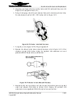
NOTE: Install the pushrod housings nearest to engine mount
brackets first. The Pushrod Spring Compressor Tool must lie close
to horizontal to clear the crankcase flange.
7.
Using a Borrough's 68-3 Pushrod Spring Compressor (Special Tools and Supplies,
Chapter 3) or equivalent, compress the pushrod tube spring.
8.
Place a new packing between the two steel washers, and install on the
crankcase
end
of the pushrod housing.


