Non-Overhaul Removal and Replacement
Teledyne Continental Motors, Inc.
TM
10-36
IOF-550 Permold Series Engine Maintenance Manual
1 April 2007
10.
Check the resistance between the connector(s) header and the body of each of the
Fuel Pressure and Manifold Air Pressure (MAP) Sensors. The resistance must be less
than 0.5 ohms.
11.
Apply a new seal to the connector header, adhesive side contacting the header. Trim
any seal overhang flush with header shell. Smooth all wrinkles from seal.
12.
Apply a thin film of Dow Corning #4 electrical grease around the metal portion of the
connector header (area prepared in steps 4 & 5).
13.
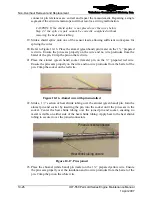
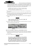
Place the EMI gasket in position over the connector header with the notched edge of
the gasket facing up (Figure 10-32 and Figure 10-33).
Notched Edge
Sealant Strip
EMI Gasket
Notched Edge
Sealant Strip
EMI Gasket
Figure 10-32.
EMI Gasket and Seal (where arrow is) in Position on ECU
Header Shell
25 Pin
Connectors
Header Shell
25 Pin
Connectors
Figure 10-33.
SSA Signal Conditioner EMI Gasket and Seal in Position
WARNING
Do not attempt to repair a connector on the engine low voltage
harness in the field. The connectors are assembled with special
tools with RTV and sealed with high-temperature adhesives.
14.
Carefully align the connector with the header. Notice the connector has tapered side
edges (as shown in Figure 10-32). Match and mate the narrower edges of the
connector and header and press firmly on the backshell to seat the connector on the
header.


