Teledyne Continental Motors, Inc.
TM
Non-Overhaul Removal and Replacement
IOF-550 Permold Series Engine Maintenance Manual
10-27
1 April 2007
24.
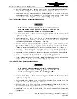
Place the chromel (white band) socket (female) pin on the
⅝
” prepared red wire.
Ensure the pin seats properly on the wire and no wire protrudes from the barrel of the
pin. Crimp the socket on the white wire.
Figure 10-18.
Chromel wires with pins
WARNING
Hot air guns are capable of producing levels of heat sufficient
to ignite combustible materials found in the aircraft engine
nacelle. Thoroughly clean the work area of oil or grease
residue. Cap or close all fuel sources. Thoroughly dry open fuel
spills before using the hot air gun. Shield components and
wiring in proximity to the item being heated.
25.
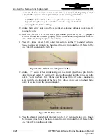
Slide a 1 ½” section of heat shrink tubing over the chromel (white band) pin. Join the
chromel pin and socket by inserting the pin into the socket until the pin seats in the
socket. Center the heat shrink tubing over the joined pin and socket, ensuring no
metal is visible on either side of the heat shrink tubing. Apply heat to the heat shrink
tubing to secure it over the joined connectors.
CAUTION: Failure to use the appropriate splicing barrel for each
EGT wire will result in abnormal engine operation and may cause
engine damage.
Heat shrink tubing shrunk to splice
No exposed
conductors
Heat shrink tubing shrunk to splice
No exposed
conductors
Figure 10-19.
EGT Wire Splice
26.
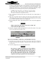
Center the shield splice over the wire splices and the braided shield.
27.
Apply heat to the center of the sleeve until the solder melts and the shield tubing
shrinks.
28.
Progressively move heat toward one end of the shield splice slowly to keep the sleeve
shrinking as the heat is moved outward.
29.
Apply heat for an additional 5 to 10 seconds to the final ½-inch of the sleeve shield to
ensure sufficient heat transfer to the cable shield for a good bond.

