Non-Overhaul Removal and Replacement
Teledyne Continental Motors, Inc.
TM
10-28
IOF-550 Permold Series Engine Maintenance Manual
1 April 2007
30.
Repeat the previous two steps for the other end of the sleeve.
31.
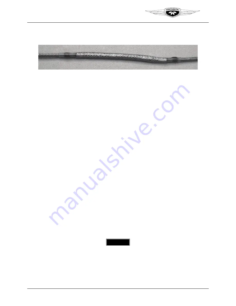
The splice is now complete and should resemble Figure 10-20.
Figure 10-20.
Completed EGT Sensor Lead Wire Splice
32.
Inspect the continuity of the sensor lead wires. If the inspection reveals poor
continuity readings and/or if any wire appears damaged, isolate the faulty wiring and
repeat the procedure.
33.
If splice was for wire repair, proceed to step 34. If sensor was removed for
replacement, install the EGT sensor according to instructions in Section 10-6.20
“Exhaust Gas Temperature Sensor Installation.”
34.
If all lead wiring is intact, bundle the sensor leads as required. For proper operation of
the engine, route, clamp, support, and protect the wires in the low voltage harness in a
manner to prevent chafing, fretting, and wear of the lead wires. Route and secure the
harness as described in “Harness Routing” section of Appendix C.
CAUTION: Avoid making sharp bends or kinks in the lead wires.
35.
Perform a FADEC Level I Diagnostics according to instructions in Chapter 8,
Troubleshooting. Pay particular attention to the sensor output for the repaired circuit.
10-5.2. Non-EGT Sensor and Lead Wire Replacement
Equipment Required:
•
Crimping tool
•
Non-EGT Sensor/Wire Splice Kit
•
Utility knife
•
Scissors
•
A variable intensity heat gun with a small tip
Prerequisites:
Before proceeding, review Sections 10-1, “Parts Replacement” and 10-5, “Engine Low
Voltage Harness Lead Wire Repair and Sensor Replacement.”
Procedure
WARNING
If power is not disconnected, a loose or broken wire could
allow the engine to start and the propeller to rotate. Do not
stand or place equipment within the arc of the propeller.
1.
Disconnect electrical power to the engine; turn the Ignition Switch OFF.

