Teledyne Continental Motors, Inc.
TM
Maintenance
Inspections
4.
Inspect the cleaned filter; verify the filter is clean and free of dents or damage. If the
filter is damaged, replace it with a new filter.
5.
Install the filter (101) in the fuel distribution block body (103) with a new O-ring
(100) and new gasket (102).
6.
Install and secure the cover with four each screws (96), new lock washers (97), and
washers (98) (Figure 7-24); torque per Appendix B.
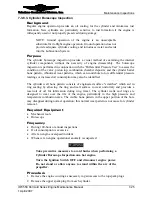
7-3.14.1.2. IOF-550-N, P and R Fuel Distribution Block Service
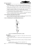
Figure 7-24.
Fuel Distribution Block Assembly
26 Washer
103 Screw
110 Washer
97 Bracket
104 Lock
washer 111
Isolator
plate
98 Cover
105 Screw
112 Isolator
plate
base
Distribution Block Body
106 Spacer
113 Screw
100 O-ring
107 Rivet
114 Orifice
fitting
101 Screen
108 Nut
plate
115 45°
elbow
102 O-ring
109 Screw
Procedure
1.
Disconnect and cap the fuel return line to the distribution block assembly.
2.
Disconnect the electrical connectors from the fuel pressure sensors; leave the orifice
fitting (114) intact on the cover (98).
3.
Remove the three screws (Figure 7-24) (103 and 113), lock washers (104), and
washers (26) from the fuel distribution block cover (98).
4.
Remove the cover O-ring (102), filter (101), and filter O-ring (100); discard the O-
rings.
5.
Clean the fuel distribution block body (99), cover (98), and filter (101) according to
“Cleaning” instructions in Chapter 9.
6.
Inspect the filter (101) for serviceability; replace if damaged.
7.
Install the filter in the fuel distribution block (99) with new O-rings (100 and 102).
IOF-550 Permold Series Engine Maintenance Manual
7-39
1 April 2007

