Teledyne Continental Motors, Inc.
TM
Non-Overhaul Removal and Replacement
IOF-550 Permold Series Engine Maintenance Manual
10-85
1 April 2007
10-8.5.3. IOF-550-N, P, and R Cylinder Service Limits
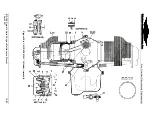
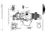
Refer to the Service Limits in Table 10-12 and corresponding Figure 10-65 and Figure
10-66. Clean and dry the parts thoroughly according to TCM Overhaul Manual (OH-24)
Chapter 8, “Engine Cleaning” instructions. Remove all oil and preservative material
before performing the dimensional inspection. Discard and replace parts that do not
conform to the specified tolerances.
WARNING
Use only parts that meet the specified service limits.
Table 10-12.
Cylinder Assembly Fits and Limits
Item # Description
Service
Limit
New Part
Minimum
(inches)
New Part
Maximum
(inches)
Cylinder Assembly
Cylinder bore (lower 4-1/4 inch of barrel) diameter Figure 10-66
Cylinder bore choke (at 5.75 inch from open end
of barrel) taper
Figure 10-66
Cylinder bore out-of-round
0.003
0.0000
0.0010
Cylinder bore – allowable oversize
Figure 10-66
Cylinder bore surface (Nitrided Barrels) Cross
hatch angle
Finish in micro-inches R
a
22° - 32°
30-50
22° - 32°
35
—
60
Cylinder barrel in crankcase diameter
0.013L
0.0040L
0.0100L
Intake valve seat insert in cylinder head diameter
0.007T
0.007T
0.010T
Intake valve guide in cylinder head diameter
0.001T
0.0010T
0.0025T
Exhaust valve guide in cylinder head diameter
0.001T
0.0010T
0.0025T
Exhaust valve seat insert in cylinder head
diameter
0.007T 0.0070T 0.0100T
Intake valve seat width
Exhaust valve seat width
Exhaust valve seat-to-valve guide axis angle
45° 00'
44° 30'
45° 00'
Intake valve seat-to-valve guide axis angle
60° 15'
59° 30'
60° 00'
Rocker Arms and Shafts
Rocker shaft in cylinder head bosses diameter
0.0040L
0.0005L
0.0031L
Rocker shaft in rocker arm bushing diameter
0.0040L
0.0005L
0.0031L
Rocker arm bushing bore diameter
Rocker arm bushing inside diameter – finish bore
0.8755
0.7515
0.8725
0.7505
0.8755
0.7515
Rocker arm side clearance
0.0150L
0.0020
0.0150
Intake valve guide inside diameter
Intake valve in guide diameter
0.0050L
0.4350
0.0010L
0.4362
0.0032L
Exhaust valve guide inside diameter
Exhaust valve in guide diameter
0.0062L
0.4370
0.0029L
0.4380
0.0046L
Intake valve face-to-stem axis angle
60°15'
60°00'
60°15'
Exhaust valve face-to-stem axis angle
45°30'
45°00’
45°15'
Intake valve gauge line-to-stem length
4.714
Exhaust valve face-to-stem length
Replace 100%
Intake valve face-to-stem runout
0.0015
0.0000
0.0015


