background image

Teledyne Continental Motors, Inc.

TM

 Troubleshooting 

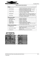
Table 8-4.


System Status Indicators 

Engine 

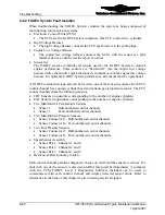
 Excessive CHT 

Cylinder head temperature is above engine’s maximum 
limit; may not be a FADEC System fault 

 Excessive EGT 

Exhaust gas temperature is above engine’s maximum 
limit; may not be a FADEC System fault. 

 Engine running 

There are more than 125 milli-seconds between Ne 
events with the engine is running. 

 Dead cylinder 

Cylinder head temperature is below level indicative of an 
operational cylinder; may not be a FADEC System fault. 


 Lean misfire 

Exhaust gas temperature indicates normal combustion is 
not occurring in a given cylinder. 

Channel Performance 

N

e

 task overrun 

High level controller fault 

A/D conversion fault 

High level controller fault 

ISR overrun 

High level controller fault 

Reset detected 

High level controller activity 

Fuel pump short 

Shorted fuel pump has been detected 


Backup injection 

Channel is performing the injection function for the other 
channel residing in the same ECU. 

Discrete Control Functions 

Fuel pump latch 

Fuel pump control is latched in the ON state. Suspect 
engine driven pump fault 

Ignition Switch enabled 

Ignition switch is in the enabled position for the channel 
(position L or R). 


Fuel pump ON 

Aircraft boost pump control commanded ON 


IOF-550 Permold Series Engine Maintenance Manual 

8-19 

1 April 2007 

Содержание Permold IOF-550-B

Страница 1: ...F 550 B C N P R Publication M 24 Change 1 2007 TELEDYNE CONTINENTAL MOTORS INCORPORATED OCT 2007 CONTINENTAL AIRCRAFT ENGINE PERMOLD SERIES ENGINE MAINTENANCE MANUAL TECHNICAL PORTIONS APPROVED BY THE FAA ...

Страница 2: ... 0 1 1 thru 1 10 0 2 1 thru 2 34 0 2 35 1 2 36 thru 2 42 0 3 1 thru 3 38 0 4 1 thru 4 2 0 5 1 thru 5 2 0 6 1 thru 6 16 0 7 1 thru 7 3 0 7 4 1 7 5 thru 7 62 0 8 1 thru 8 58 0 9 1 thru 9 30 0 10 1 thru 10 108 0 A 1 thru A 8 0 B 1 thru B 12 0 C 1 thru C 22 0 Published and printed in the U S A by Teledyne Continental Motors Available exclusively from the publisher P O Box 90 Mobile AL 36601 Copyright ...

Страница 3: ...placement N A N A M87 15 Alternator Ground Strap Alternator Replacement Alternator Repair Chapter 10 M88 9 Lightning Strikes Unscheduled Maintenance Inspections Chapter 7 M88 10 Contaminated Fuels Unscheduled Maintenance Inspections Chapter 7 M89 9 Excessive Crankcase Pressure Unscheduled Maintenance Inspections Chapter 7 M90 13 Exhaust Valve Stem Corrosion Erosion Inspection and Overhaul N A N A ...

Страница 4: ...pecifications Scheduled Maintenance Overhaul Periods Chapter 7 SIL99 1 Engine Preservation for Active and Stored Aircraft Engine preservation and returning an engine to service after storage Placing an Engine in Service After Storage N A SIL99 2B Current Listing of Sealants Lubricants and Adhesives Authorized by TCM Materials Engine Operation in Extreme Cold Throughout SB99 8 Engine Fuel Injection...

Страница 5: ...eased After Publication TCM strives to provide clear concise and accurate information and instructions based on best known engineering data at the time of publication Ongoing process improvements at TCM may change a specification or procedure after a manual is released Service Documents defined in Chapter 1 expedite customer notification and serve as the prevailing instruction over conflicting inf...

Страница 6: ...ne Maintenance Manual 1 April 2007 Mandatory and Critical Service Documents Published After this Manual Document Number Title Affected Section s in this Manual Other Service Documents Published After This Manual Document Number Title Affected Section s in this Manual ...

Страница 7: ... use is authorized Installation of non TCM parts on a TCM engine constitutes a deviation from TCM type design criteria TCM has not participated in design test or certification of any non TCM parts TCM does not provide product manufacturing specifications to aftermarket parts manufacturers and accepts no liability for the suitability durability longevity or safety of such parts installed on TCM eng...

Страница 8: ...nt 10 1 Appendix A Glossary A 1 Appendix B Torque Specifications B 1 Appendix C Standard Practices C 1 OVERHAUL MANUAL OH 24 Chapter 1 Introduction 1 1 Chapter 2 Engine Description 2 1 Chapter 3 Special Tools and Supplies 3 1 Chapter 4 Airworthiness Limitations 4 1 Chapter 5 Engine Removal and Installation 5 1 Chapter 6 Engine Disassembly 6 1 Chapter 7 Component Disassembly 7 1 Chapter 8 Engine Cl...

Страница 9: ...e and Purpose of This Manual 1 2 1 1 1 Effectivity Symbols 1 3 1 1 2 Advisories 1 3 1 1 3 Using this Manual 1 3 1 1 4 Compliance 1 4 1 1 5 Order of Precedence 1 5 1 2 Publications 1 6 1 2 1 Service Documents 1 6 1 2 2 Related Publications 1 7 1 2 3 Publication Access 1 8 1 2 4 Publication Changes 1 8 1 3 TCM Contact Information 1 9 LIST OF TABLES Table 1 1 Related Publications 1 7 ...

Страница 10: ...maintenance manual provides general maintenance information including maintenance schedules inspection and service requirements troubleshooting and repair procedures The overhaul manual provides detailed engine overhaul instructions to return the engine to like new specifications The maintenance section begins with administrative instructions regarding access to TCM publications and a list of othe...

Страница 11: ...ocedure or operation of equipment Warnings and cautions precede the steps to which they apply notes are placed in the manner which provides the greatest clarity Warnings cautions and notes do not impose undue restrictions Failure to heed advisories will likely result in the undesirable or unsafe conditions the advisory was intended to prevent Advisories are inserted to ensure maximum safety effici...

Страница 12: ...hedule Failure to comply may void the engine warranty WARNING Prior to authorizing engine installation or maintenance the owner must ensure the mechanic meets the requirements of FAR 65 and must follow FAR parts 43 91 and 145 as applicable Except for FAR part 43 3 authorized owner maintenance TCM ICAs are written for exclusive use by FAA or equivalent authority licensed mechanics or FAA or equival...

Страница 13: ...ired to satisfy a specific aircraft engine installation WARNING The aircraft operator must use the airframe manufacturer s operating instructions found in the Airplane Flight Manual Pilot s Operating Handbook AFM POH while operating the aircraft unless the AFM POH directs otherwise Refer to the AFM POH published by the airframe manufacturer for operating instructions and specifications relative to...

Страница 14: ...pdates to TCM s Instructions for Continued Airworthiness to address a safety issue Category 2 Critical Service Bulletin CSB This category identifies a condition that threatens continued safe operation of an aircraft persons or property on the ground unless some specific action inspection repair replacement etc is taken by the owner or operator Documents in this category are candidates for incorpor...

Страница 15: ... Manual OI 24 Yes Yes Yes N A Overhaul Manual OH 24 No Yes Yes N A Starter Service Instructions X30592 No Yes Yes N A Lightweight Starter Service Instructions STR 01 No Yes Yes N A Alternator Service Instructions X30531 3 No Yes Yes N A Parts Catalogues No Yes No N A Detailed Model Specifications No No Yes N A Service Documents No Yes Yes N A Material Handling Specifications MHS No No Yes N A Supp...

Страница 16: ...ed information to the customer in the most expedient manner WARNING New information may be contained in Teledyne Continental Motors service documents Service documents applicable to engines and accessories within the scope of this manual must be complied with as defined in these documents This manual together with TCM s Installation and Operation Manual OI 24 Overhaul Manual OH 24 Service Document...

Страница 17: ...ce immediately using our toll free number if you discover incorrect information which adversely affects safety 1 3 TCM Contact Information Teledyne Continental Motors is available to answer technical questions and encourages suggestions regarding products parts or service If customers have an inquiry or require technical assistance they should contact their local TCM distributor or TCM field repre...

Страница 18: ...Introduction Teledyne Continental Motors Inc TM 1 10 IOF 550 Permold Series Engine Maintenance Manual 1 April 2007 This Page Intentionally Left Blank ...

Страница 19: ...bly 2 27 2 2 8 Alternator 2 27 2 2 9 Engine Cooling 2 28 2 2 10 Induction System 2 29 2 2 11 Exhaust 2 30 2 3 Engine Specifications and Operating Limits 2 30 2 3 1 IOF 550 B Specifications and Operating Limits 2 31 2 3 2 IOF 550 C Specifications and Operating Limits 2 33 2 3 3 IOF 550 N P and R Specifications and Operating Limits 2 35 2 3 4 Accessory Drive Ratios 2 37 2 3 5 Oil Specifications 2 37...

Страница 20: ... 13 Two Lamp HSA Panel 2 21 Figure 2 14 HSA with Battery Condition Monitor Panel 2 21 Figure 2 15 Engine Control Panel 2 22 Figure 2 16 Engine Data Interface 2 22 Figure 2 17 IOF 550 B C Fuel Injection System 2 23 Figure 2 18 IOF 550 N P R Fuel Injection System 2 24 Figure 2 19 Fuel Pump 2 25 Figure 2 20 FADEC Fuel Injector and Solenoid 2 26 Figure 2 21 Starting System 2 27 Figure 2 22 Engine Cool...

Страница 21: ...ing on airframe requirements Permold engines utilize either a cast aluminum or stamped aluminum oil sump attached to the bottom of the crankcase The engine is provided with four engine mounts designed for a focalized bed mount an optional six point mount is available A crankcase breather port is located on the oil filler neck on the 2 4 6 side of the crankcase between number 2 and number 4 cylinde...

Страница 22: ...izontally Opposed Cylinders Specification Number Model Identifier Cubic Inch Displacement FADEC equipped Fuel Injected B Shipping Designation Figure 2 1 Engine Model Identifier 2 1 2 Cylinder Number Designations Refer to Figure 2 2 The front of the engine is the end closest to the propeller and the rear of the engine is the accessory end Viewed from the rear of the engine the left side cylinders a...

Страница 23: ...addle for the starter adapter and needle bearing Cylinder mounting pads on the left crankcase are farther forward than the corresponding pads on the right crankcase to permit each connecting rod to work on a separate crankpin There are seven studs and two through bolts for attaching cylinder base flanges The propeller governor mount pad located on the left hand lower front corner of the left crank...

Страница 24: ...s in a counter clockwise direction to drive the magneto drive gears Optional accessories mounted on the aft side of the accessory case are driven by the internal splines of the magneto drive gears The fuel pump coupling is connected directly to the crankshaft gear The splined end of the oil pump drive gear mates with the internal splines of the camshaft gear and transmits torque to the oil pump dr...

Страница 25: ... gear is heated prior to installation to obtain a shrink fit The gear is positioned on the crankshaft by a dowel pin it incorporates a square output coupling to direct drive fuel pump The gear also has a machined timing mark to properly position the crankshaft and camshaft angles The alternator drive gear is attached by a flange just behind the number 5 main journal at the front of the crankshaft ...

Страница 26: ... the eccentric camshaft lobes The lobes and journals are ground and hardened Movement of the tappets opens and closes the intake and exhaust valves within the cylinder head by mechanical linkage of the pushrods and rocker arms The exact moment of valves opening and closing is synchronized by the crankshaft to camshaft timing Four unequally spaced bolts retaining the gear to the camshaft ensure pro...

Страница 27: ... holds two concentric springs which surround the intake valve which is locked to the stem by tapered semi circular keys which engage grooves on the stem The IOF 550 B and C engine cylinder head design has intake and exhaust ports located on the bottom of the cylinder as installed on the engine This design is referred to as an updraft configuration Figure 2 6 The valve rocker cover is one piece mad...

Страница 28: ...OCKER ARM RETAINER THRUST WASHER ONE ON EACH SIDE OF EACH ROCKER ARM Figure 2 6 Updraft Cylinder Assembly ROCKER SHAFT ROCKER ARM VALVE RETAINER KEYS ROTOCOIL EXHAUST VALVE GUIDE OUTER SPRING INNER SPRING SPRING SEAT INTAKE VALVE GUIDE INTAKE VALVE SEAT INSERT INTAKE VALVE CYLINDER BARREL EXHAUST VALVE COOLING FINS CYLINDER HEAD CYLINDER BARREL COOLING FINS CYLINDER BASE FLANGE CYLINDER SKIRT ROCK...

Страница 29: ...ly via push rod tubes and rocker arms This allows conversion of the cam lobe profile into a linear movement for actuation of the intake and exhaust valves Secondly the hydraulic mechanism inside the lifter maintains zero clearance between the valve and it s actuating components The interface between a cam lobe and lifter is intended to wear to some degree as the engine operates This is similar to ...

Страница 30: ...hen falls to the lower rocker cavity and returns to the crankcase and sump through the pushrod housings Oil from the left main crankcase gallery is also directed upward through crankcase oil passages to the crankshaft main bearings and idler gear bushing Oil is directed upward from the idler gear bushing to both accessory drive bushings Oil lubricating the crankshaft mains is directed through the ...

Страница 31: ... gear meshes with the driven gear to turn it clockwise The rotating gears create a suction that draws oil from the sump through the oil suction tube to the pump gear inlet Oil flows from the oil pump to the oil filter housing and filter element The oil is then directed through the element down through a passage in the oil pump housing and out to the right crankcase main oil gallery A by pass is in...

Страница 32: ...d crankshaft position information to the Engine Control Units through the engine low voltage harness 2 2 4 3 Oil Cooler and Oil Temperature Control Valve Oil flowing from the oil pump enters the oil cooler inlet where it is directed upward to the cooler core by the cast oil gallery When the oil is below normal operating temperature the oil temperature control valve vernatherm is open allowing oil ...

Страница 33: ... VALVE CLOSED OIL HOT OIL IN FROM OIL PUMP OIL OUT TO ENGINE OIL FLOW OIL HOT COOLING FINS COOLING CORE STATIC OIL VALVE OPEN OIL COLD OIL OUT TO ENGINE OIL FLOW THRU BY PASS OIL COLD STATIC OIL BY PASS OIL COLD OIL IN FROM OIL PUMP OIL OUT TO ENGINE OIL TEMPERATURE CONTROL VALVE VERNATHERM LIMITED OIL FLOW OIL COLD Figure 2 10 Oil Cooler ...

Страница 34: ...are installed can communicate real time with each control channel to determine specific information regarding detected sensor faults to be obtained 2 2 5 1 Electronic Control Units Six cylinder engines employ three Electronic Control Units ECU one for cylinder pair The ECUs control fuel mixture and ignition timing for respective engine cylinders ECU 1 controls opposing cylinders 1 and 2 ECU 2 cont...

Страница 35: ...J3 J4 P1 P2 P3 P4 P5 J1 J2 CHT Sensor EGT Sensor Fuel Injector Solenoid Manifold Air Pressure Sensors Manifold Air Temperature Sensors Fuel Pressure Sensors Speed Sensor Assembly mounted in oil sump adjacent to camshaft J1 J2 Left Sump Connector Channel A Nc1 Nc2 Nc3 Channel B Right Sump Connector TO ECU Channel A processor Channel B processor Even numbered cylinder signals Primary Input Odd numbe...

Страница 36: ...ion Switch BP BE Switch HSA ECP P2 P3 P1 P4 P5 6 EGT Sensor Fuel Injector Solenoid CHT Sensor ECU 3 5T 6B 6T 5B 5 6 EGT Sensor Fuel Injector Solenoid CHT Sensor ECU 3 5T 6B 6T 5B ECU 3 ECU 3 5T 6B 6T 5B 5 Manifold Air Pressure Sensors Manifold Air Temperature Sensors Fuel Pressure Sensors Speed Sensor Assembly mounted in oil sump adjacent to camshaft J1 J2 J4 J3 Left Sump Connector Channel A Nc1 N...

Страница 37: ...e per engine cycle once on the compression stroke and again on the exhaust stroke The ECU emits a high voltage pulse through the high voltage harness to fire the top spark plug on the compression stroke and the bottom spark plug on the exhaust stroke for the opposite cylinder Ignition spark is mechanically synchronized with the engine s crankshaft position and retarded and advanced throughout the ...

Страница 38: ...nder via a bayonet style adapter which threads into the cylinder head A spring loaded locking ring on the sensor reinforces this attachment The CHT Sensor is hardwired to the Engine Low Voltage Harness Each CHT Sensor is independent and operates for a respective engine cylinder The sensing element in the CHT Sensor is a thermistor This type of device changes resistance with temperature in a linear...

Страница 39: ...tion Options Multiple indication options are available for crew compartment displays ranging from simple lamp driver circuits to multiple line LCD control panels 2 2 5 12 1 Health Status Annunciator The two lamp HSA panel has a red FADEC warning lamp Figure 2 13 and a yellow FADEC caution lamp The warning lamp will illuminate if a malfunction exists with any combination of non opposing cylinder pa...

Страница 40: ...ctions are integrated into the ECP TEST A and TEST B buttons The Ignition Switch start and off functions are also incorporated into the ECP See Chapter 7 Engine Operation for additional information Figure 2 15 Engine Control Panel 2 2 5 12 3 Engine Data Interface The optional Engine Data Interface EDI is a crew compartment mounted RS 232 data terminal with storage capability The EDI has red and gr...

Страница 41: ...system incorporates a bypass valve in the fuel filter and a heat isolator under the fuel distribution block to accomplish the same result FUEL PUMP CONTROL SIGNAL FROM BOOST PUMP VARIABLE PULSEWIDTH CONTROLS AMOUNT OF FUEL CONTROL PULSE FROM FADEC MPC FUEL INJECTOR NOZZLE FUEL PRESSURE SENSORS FUEL DISTRIBUTION BLOCK 20 MICRON FILTER 10 MICRON FILTER GROUND FUEL PUMP OUTLET PRESSURE FUEL INLET FRO...

Страница 42: ...PLY LEGEND FUEL PUMP OUTLET PRESSURE FUEL INLET FROM AIRCRAFT SUPPLY RETURN TO AIRCRAFT SUPPLY LEGEND 10 MICRON FILTER ORIFICE FITTING 32 FUEL PUMP VARIABLE PULSEWIDTH CONTROLS AMOUNT OF FUEL CONTROL PULSE FROM FADEC MPC FUEL INJECTOR NOZZLE FUEL PRESSURE SENSORS FUEL DISTRIBUTION BLOCK 20 MICRON FILTER FUEL PUMP OUTLET PRESSURE FUEL INLET FROM AIRCRAFT SUPPLY RETURN TO AIRCRAFT SUPPLY LEGEND 10 M...

Страница 43: ... outlet fuel travels through various fittings and fuel lines to the fuel distribution block and fuel injector nozzles The positive displacement engine driven fuel pump varies the amount of fuel delivered to the manifold in proportion with engine speed changes The fuel pump is sized to provide greater capacity than the engine requires An integral aneroid valve functions to increase pump output pres...

Страница 44: ...ylinder The fuel injector is threaded on both ends outlet screws into the tapped fuel injector boss in the cylinder head The fuel injector assembly is made up of two parts the control coil and the injector nozzle Figure 2 20 The internal components of the fuel injector nozzle consist of a pintle valve and a spring The solenoid creates an electromagnetic field to lift the pintle valve and open the ...

Страница 45: ... from the starter motor The gripping action of the clutch spring is relieved disengaging the shaftgear from the worm shaft and electric starter motor The starter shaftgear extends from the rear of the starter adapter STARTER WORM WHEEL STARTER SHAFTGEAR STARTER WORM GEAR STARTER MOTOR STARTER WORM GEAR SHAFT CRANKSHAFT GEAR Figure 2 21 Starting System 2 2 8 Alternator The standard configuration ge...

Страница 46: ...ng baffles and baffle seals direct cooling air which is ram air induced by the aircraft s forward speed evenly around the cylinders This airflow is regulated by the size of the cooling air inlets and outlets Increasing or decreasing outlet size with the use of cowl flaps changes airflow and is used as an aid in controlling engine operating temperatures HIGH PRESSURE AREA LOW PRESSURE AREA AIRCRAFT...

Страница 47: ...VIEW OF ENGINE WITH INDUCTION MANIFOLD INSTALLED BALANCE TUBE INDUCTION RISER AIR FILTER AIR THROTTLE VALVE INDUCTION RUNNER INDUCTION RISER INDUCTION RUNNER Figure 2 23 IOF 550 B Updraft Induction Airflow The IOF 550 N P and R Figure 2 24 Induction System carries induction air to individual cylinder intake ports through a cross flow cylinder head design A downdraft type Induction System is mounte...

Страница 48: ...D INDUCTION MANIFOLD INDUCTION TUBES INDUCTION TUBES Figure 2 24 Downdraft Crossflow Induction Airflow 2 2 11 Exhaust The IOF 550 exhaust system is provided by the customer 2 3 Engine Specifications and Operating Limits Specifications and operating limits differ between IOF 550 models Refer to the tables representing the subject engine for correct model specifications ...

Страница 49: ...ngine accessory load Standard day conditions are 29 92 in Hg and 59 F Horsepower will vary approximately 1 for each 10 F 5 6 C change in throttle inlet air temperature Correction must also be made for the effect of exhaust backpressure and accessory drive losses Contact TCM engineering for correction factors for specific applications FUEL SYSTEM SPECIFICATIONS Fuel Control System FADEC Electronic ...

Страница 50: ... Cruise Flight Operation Oil Temperature 170 to 220 F 77 to 104 C Oil Sump Capacity 12 0 Quarts Useable Oil 16 Nose Up 12 quart fill 7 7 Quarts Useable Oil 10 Nose Down 12 quart fill 7 3 Quarts Recommended Oil Grade SAE above 40 F 50 or Multi Viscosity Recommended Oil Grade SAE below 40 F 30 or Multi Viscosity Oil Grade TCM Specification MHS 24 CAUTION Oil must be aviation oil conforming to MHS 24...

Страница 51: ...ngine accessory load Standard day conditions are 29 92 in Hg and 59 F Horsepower will vary approximately 1 for each 10 F 5 6 C change in throttle inlet air temperature Correction must also be made for the effect of exhaust backpressure and accessory drive losses Contact TCM engineering for correction factors for specific applications FUEL SYSTEM SPECIFICATIONS Fuel Control System FADEC Electronic ...

Страница 52: ...Cruise Flight Operation Oil Temperature 170 to 220 F 77 to 104 C Oil Sump Capacity 12 0 Quarts Useable Oil 16 Nose Up 12 quart fill 6 9 Quarts Useable Oil 10 Nose Down 12 quart fill 6 3 Quarts Recommended Oil Grade SAE above 40 F 50 or Multi Viscosity Recommended Oil Grade SAE below 40 F 30 or Multi Viscosity Oil Grade TCM Specification MHS 24 CAUTION Oil must be aviation oil conforming to MHS 24 ...

Страница 53: ...the throttle inlet and exhaust exit with no engine accessory load Standard day conditions are 29 92 in Hg and 59 F Horsepower will vary approximately 1 for each 10 F 5 6 C change in throttle inlet air temperature Correction must also be made for exhaust backpressure and accessory drive losses Contact TCM engineering for specific application correction factors FUEL SYSTEM SPECIFICATIONS Fuel Contro...

Страница 54: ...pacity 16 Nose Up 5 0 Quarts 7 8 Quarts 7 5 Quarts Oil Sump Capacity 10 Nose Down 4 5 Quarts 6 7 Quarts 7 3 Quarts Recommended Oil Grade SAE above 40 F 50 or Multi Viscosity Recommended Oil Grade SAE below 40 F 30 or Multi Viscosity Oil Grade TCM Specification MHS 24 CAUTION Oil must be aviation oil conforming to MHS 24 Oil pressure and temperature are measured at the oil cooler adapter BRAKE SPEC...

Страница 55: ...s not exceed 100 in lb continuous torque load Drive pads are per AND 20000 optionally per MS3325 modified and shall be provided with covers This drive is a modified AND 20010 and shall be supplied with a cover 2 3 4 1 Accessory Drive Pad The accessory drive pad is an AND20000 specification that has been modified for speed torque and moment The drive pad is provided with a cover in the event that i...

Страница 56: ...r MHS 24 Lubricating oils classified by the North Atlantic Treaty Organization NATO Standardization Agreement STANAG as interchangeable with oils qualified under J1899 or J1966 and assigned NATO Codes 0 123 and 0 128 are also qualified under MHS 24 2 3 6 Performance Data Refer to the applicable TCM Detailed Model Specification for complete engine technical specifications installation requirements ...

Страница 57: ...1 IOF 550 B and C Performance Charts 40 50 60 70 80 90 100 110 120 130 140 150 160 170 180 120 130 140 150 160 170 180 190 200 210 220 230 240 250 260 270 280 290 300 310 320 OBSERVED BRAKE HORSEPOWER FUEL FLOW lb hr Hot Head Prop Load Max Rich Normal Prop Load 55 65 75 Figure 2 25 IOF 550 B and C Fuel Flow vs Brake Horsepower ...

Страница 58: ...ke Horsepower TO DETERMINE ACTUAL HP 1 Locate RPM Pm on Altitude Chart Pt A 2 Locate RPM Pm on Sea Level Chart Pt B 3 Transfer B to Sea Level on Altitude Chart Pt C 4 Draw line Y from C through A 5 Locate Pt D at ambient Pressure Altitude 6 Draw vertical line through Z through D 7 Read HP from intersection of Y and Z Correct HP for inlet air Add 1 for each 10 below standard altitude temp Ts Subtra...

Страница 59: ... 190 200 210 220 230 240 250 260 270 280 290 300 310 320 330 45 Rated Power 55 Rated Power 65 Rated Power 75 Rated Power 85 Rated Power Note Best Economy values are optmized values Best Power values at and below 85 power are optimized values Note Full Rich is all 6 cylinders in hot head operation Full Rich BP Sw itch Position Full Rich BE Sw itch Position Best Economy Best Pow er Figure 2 27 IOF 5...

Страница 60: ...Horsepower CBHP Note Speed Lines in 100 RPM Steps 2100 RPM 2700 RPM To determine actual HP 1 Loc RPM Man PR on Alt Chart Pnt A 2 Loc RPM Man PR on Alt Chart Pnt B 3 Transfer B to SL on Alt Chart Pnt C 4 Draw line Y from C thru A 5 Locate pt D at ambient pressure alt 6 Draw Vertical line Z thru D 7 Read HP from intersection of lines Y Z 8 Corr H P for inlet air as follow s A Add 1 for each 10 F bel...

Страница 61: ...8 LIST OF FIGURES Figure 3 1 Model E2M Differential Pressure Tester built in Master Orifice Tool 3 13 Figure 3 2 Model E2A Differential Pressure Tester no Master Orifice Tool 3 13 Figure 3 3 Master Orifice Tool used with pressure tester E2A 3 14 Figure 3 4 Borescope Autoscope 3 14 Figure 3 5 Helical Coil Extraction Tool 3 15 Figure 3 6 Helical Coil Insertion Tool 3 15 Figure 3 7 Helical Coil Expan...

Страница 62: ... Jaw Dimensions 3 25 Figure 3 23 Staking Tool Overall Dimensions 3 26 Figure 3 24 Bearing Installation Tool 3 27 Figure 3 25 Crankcase Needle Bearing Installation Tool 3 27 Figure 3 26 Valve Guide Seat Installation Tool 3 28 Figure 3 27 O Ring Installation Tool 3 28 Figure 3 28 Oil Seal Tool 3 29 Figure 3 29 Alternator Drive Hub Holding Fixture 3 29 Figure 3 30 Alternator Drive Hub Torque Tool 3 3...

Страница 63: ...ump Operation Requirements Davis Inotek Instruments 1 1268 Setting Ring Dimensional Inspection MAHR Federal 1 1268 Air Plug Dimensional Inspection MAHR Federal Alternator Analyzer Voltage Regulator Tester Check Alternator Voltage Regulation Eastern Technology Corporation 647 Alternator Drive Hub Holding Fixture Alternator Drive Hub Slippage Inspection Fabricate per specifications in this chapter A...

Страница 64: ...e FADEC Confidence Check FADEC Level I Diagnostics Troubleshooting TCM 657205 PowerLink FADEC Serial Data Cable FADEC Confidence Check FADEC Level I Diagnostics Troubleshooting TCM 657142 Pin Test Kit Cabin Harness Functional Check Troubleshooting TCM 655857 Pulley Alignment Tool Checking Belt Sheave Alignment Borroughs 8082 Speed Sensor Assembly SSA Simulator Troubleshooting TCM 655870 Pulley pul...

Страница 65: ...orroughs 8098 Connecting Rod Bushing Installation and Removal Tool Adapter Kit Connecting Rod Piston Pin Bushing Replacement Borroughs 8042C Connecting Rod Bushing Reamer Honing The Connecting Rod Bushing Bore Kent Moore 5008 Contour Probe Magnetic Particle Inspection Parker Research Corporation DA 200 Counterweight Bushing Remover Replacer Tool Counterweight Hanger Blade Bushing Replacement Borro...

Страница 66: ...Machining Borroughs 5221B Cylinder Hone Honing an engine cylinder bore Snap On Tools CFL10 Dial Bore Gauges Dimensional inspection of bore inner diameter MAHR Federal 545 116 Dial Indicator Backlash Measurement Exhaust Valve Seat Grinding Stone Roughening 45 Intake or Exhaust Valve Seat Machining Aircraft Tool Supply K95 Exhaust Valve Seat Grinding Stone Finishing 45 Intake or Exhaust Valve Seat M...

Страница 67: ...Cylinder Bore Honing Hommel America 191800 Intake Valve Seat Grinding Stone Roughening 30 Intake or Exhaust Valve Seat Machining Aircraft Tool Supply K106 Intake Valve Seat Grinding Stone Finishing 30 Intake or Exhaust Valve Seat Machining Aircraft Tool Supply K46 Micrometers series 3 point contact inside micrometers Counterweight Hanger Blade Bushing Replacement Starrett No 78 Needle Bearing Inst...

Страница 68: ...er Step Type Rosan Stud Removal McMaster Carr Supply Company Rosan Stud Remover Rosan is a registered trademark of Fairchild Aerospace Fastener Division Rosan Stud Removal McMaster Carr Supply Company 2769A13 Rosan Lock Ring Installer Rosan Stud Installation Kent Moore 8074 Runout Block Set Drive Train Dimensional Inspection Borroughs 8117a Spark Plug Insert Remover Spark Plug Helical Coil Removal...

Страница 69: ...lacement Borroughs 3170 Valve Guide Remover Valve Guide Replacement Kent Moore 4981 Valve Guide Seal Installation Tool Engine Cylinder Assembly Fabricate per specifications in this chapter Valve Seat Grinder Set Sioux Brand Valve Seat Machining Aircraft Tool Supply 1675 Valve Seat Grinder Pilot 0 437 diameter Valve Seat Machining Aircraft Tool Supply AEX 437 Valve Seat Straight Side Insert Cutters...

Страница 70: ... www inotek com Dow Corning Corporation P O Box 997 South Saginaw Road Midand MI 48686 517 496 6000 or for distributor 800 248 2481 www dowcorning com Eastern Electronics See Eastern Technology Corporation Eastern Technology Corporation 180 Roberts St East Hartford CT 06108 1 860 528 9821 easterntech com Electro systems See Kelly Aerospace Emhart Fastening Teknologies Industrial Division 50 Shelto...

Страница 71: ...GA 31420 912 330 0500 912 330 0104 qatek com Parker Research Corporation P O Box 1406 Dunedin FL 34697 800 525 3935 1 727 797 3941 www parkreascorp co m Shell Oil Company P O Box 4320 Houston TX 77210 713 241 4819 713 241 6511 www shell lubricants com Snap On Tools 877 740 1900 877 740 1880 www snapon com L S Starrett Company 800 541 8887 978 249 3551 978 249 8495 www starrett com Tanair Tanis Air...

Страница 72: ... 3 10 Speed Sensor Assembly Simulator Figure 3 11 FADEC Timing Tool Figure 3 12 Overhaul Worm Shaft Tool and Starter Adapter Disassembly Tool Figure 3 14 Needle Bearing Installer Tool Figure 3 17 Figure 3 18 Oil Control Plug Installation Tool Figure 3 15 Oil Control Plug Leak Test Fixture Figure 3 16 Valve Gauge Line Inspection Fixture Figure 3 19 Helical Coil Extracting Tool Figure 3 5 Helical Co...

Страница 73: ...ial Tools and Supplies IOF 550 Permold Series Engine Maintenance Manual 3 13 1 April 2007 Figure 3 1 Model E2M Differential Pressure Tester built in Master Orifice Tool Figure 3 2 Model E2A Differential Pressure Tester no Master Orifice Tool ...

Страница 74: ...K PLUG THREADS 18mm DUST CAP DUST CAP Figure 3 3 Master Orifice Tool used with pressure tester E2A The Master Orifice Tool restrictor orifice dimensions for these engines must be 0 040 inch orifice diameter 0 250 inch long with 60 approach angle The airflow rate should be 120 5 cubic feet per hour at 30 psi differential pressure Figure 3 4 Borescope Autoscope ...

Страница 75: ...edyne Continental Motors Inc TM Special Tools and Supplies IOF 550 Permold Series Engine Maintenance Manual 3 15 1 April 2007 Figure 3 5 Helical Coil Extraction Tool Figure 3 6 Helical Coil Insertion Tool ...

Страница 76: ... Engine Maintenance Manual 1 April 2007 Figure 3 7 Helical Coil Expanding Tool Figure 3 8 Rosan stud Removal Tool USB to Serial Adapter EDI Serial Data Cable EDI Serial Data Cable USB to Serial Adapter EDI Serial Data Cable EDI Serial Data Cable Figure 3 9 PowerLink FADEC Serial Data Cable ...

Страница 77: ...Engine Maintenance Manual 3 17 1 April 2007 RS 485 to RS 232 Translator RS 485 to RS 232 Translator RS 485 to RS 232 Translator Figure 3 10 FADEC to PC Data Communication Cable Figure 3 11 SSA Simulator To signal conditioner To 2 4 6 side connector on sump Figure 3 12 FADEC Timing Tool ...

Страница 78: ... and Supplies Teledyne Continental Motors Inc TM 3 18 IOF 550 Permold Series Engine Maintenance Manual 1 April 2007 Figure 3 13 Pulley alignment tool Figure 3 14 Worm Shaft Tool and Starter Adapter Disassembly Tool ...

Страница 79: ...Teledyne Continental Motors Inc TM Special Tools and Supplies IOF 550 Permold Series Engine Maintenance Manual 3 19 1 April 2007 Figure 3 15 Oil Control Plug Installation Tool ...

Страница 80: ...Special Tools and Supplies Teledyne Continental Motors Inc TM 3 20 IOF 550 Permold Series Engine Maintenance Manual 1 April 2007 Figure 3 16 Oil Control Plug Leak Test Fixture ...

Страница 81: ...Teledyne Continental Motors Inc TM Special Tools and Supplies IOF 550 Permold Series Engine Maintenance Manual 3 21 1 April 2007 Figure 3 17 Needle Bearing Installation Tool Part 1 ...

Страница 82: ...Special Tools and Supplies Teledyne Continental Motors Inc TM 3 22 IOF 550 Permold Series Engine Maintenance Manual 1 April 2007 Figure 3 18 Needle Bearing Installation Tool Part 2 ...

Страница 83: ...Teledyne Continental Motors Inc TM Special Tools and Supplies IOF 550 Permold Series Engine Maintenance Manual 3 23 1 April 2007 Ø 2 50 Ø 2 50 Figure 3 19 Valve Gauge Line Inspection Tool ...

Страница 84: ...Special Tools and Supplies Teledyne Continental Motors Inc TM 3 24 IOF 550 Permold Series Engine Maintenance Manual 1 April 2007 Figure 3 20 Staking Tool Figure 3 21 Staking Tool Bill of Materials ...

Страница 85: ...Teledyne Continental Motors Inc TM Special Tools and Supplies IOF 550 Permold Series Engine Maintenance Manual 3 25 1 April 2007 Figure 3 22 Staking Tool Jaw Dimensions ...

Страница 86: ...Special Tools and Supplies Teledyne Continental Motors Inc TM 3 26 IOF 550 Permold Series Engine Maintenance Manual 1 April 2007 Figure 3 23 Staking Tool Overall Dimensions ...

Страница 87: ...pplies IOF 550 Permold Series Engine Maintenance Manual 3 27 1 April 2007 Figure 3 24 Bearing Installation Tool 5 8 NOTE ALL MEASUREMENTS STATED IN INCHES 5 8 5 8 NOTE ALL MEASUREMENTS STATED IN INCHES Figure 3 25 Crankcase Needle Bearing Installation Tool ...

Страница 88: ...al Tools and Supplies Teledyne Continental Motors Inc TM 3 28 IOF 550 Permold Series Engine Maintenance Manual 1 April 2007 Figure 3 26 Valve Guide Seat Installation Tool Figure 3 27 O Ring Installation Tool ...

Страница 89: ...ries Engine Maintenance Manual 3 29 1 April 2007 Medium Knurl Mill Flat Stamp P N On Flat 1 16 Radius 0 783 Dia 1 200 Dia 1 00 0 68 5 16 1 1 4 Dia Before Knurl 1 8x45 1 00 2 00 3 00 Material 1020 Case Harden Figure 3 28 Oil Seal Tool Figure 3 29 Alternator Drive Hub Holding Fixture ...

Страница 90: ...Special Tools and Supplies Teledyne Continental Motors Inc TM 3 30 IOF 550 Permold Series Engine Maintenance Manual 1 April 2007 Figure 3 30 Alternator Drive Hub Torque Tool ...

Страница 91: ...crometers Ballpeen hammer Allen wrenches assortment Pullers Slotted screwdrivers assortment Blind Bearing Remover Phillips screwdrivers Nos 1 and 2 Vernier calipers Safety wire pliers Leather or soft plastic mallet Common pliers Small hole gauges thickness gauges Diagonal cutter pliers Feeler gauges leaf type Needle nose pliers C clamps Duck bill pliers Brass wire brush Snap ring pliers with 90 de...

Страница 92: ...ne Continental Motors listing of accepted SAE J 1899 oils by manufacturer and brand name is for the convenience of our customers Always refer to the label on the oil to ensure that the oil meets the appropriate SAE specification QPL J 1899 Qualified Products List is available from SAE Headquarters 400 Commonwealth Drive Warrendale PA 15096 001 The Naval Air Systems Command maintains QPL J 1899 and...

Страница 93: ...l W 15W 50 Anti wear Formulation Shell USA Aeroshell Oil W 15W 50 Anti wear Formulation Shell USA Aeroshell Oil W100 Plus W80 Plus Sinclair Oil Company Sinclair Avoil Texaco Inc Texaco Aircraft Engine Oil Premium AD Total France Total Aero DM 15W 50 Union Oil Company of California Union Aircraft Engine Oil HD Table 3 6 Break in Oil TYPE EQUIVALENT APPLICATION SAE J 1966 Aviation replaces MIL L 608...

Страница 94: ...ere formulated primarily for automotive and industrial engine applications From time to time we receive inquiries regarding use of these products in our aircraft engines Most of these additives and concentrates while they may be highly beneficial to automotive and industrial operation are not compatible with air cooled light aircraft engines in their operating environments With the exception of th...

Страница 95: ...ing Nut Starter Clutch Spring ID OD Valve Guide Seals All Models Apply to sealing surface Pistons Piston Pins Piston Rings All Models Thrust Washers Oil Filter adapter seals Grade 50 Break in Non compounded Aviation Oil SAE J 1966 O Rings All Models Dow Corning G N Paste Camshaft lobes and tappet faces At engine assembly Shell Alvania 2 P N 654561 Apply a light coat at point of contact between nut...

Страница 96: ...ne Models as applicable Lubriplate 930 AA O D of Valve Guides All models at installation of guide CRC 3 36 Rust Preventative Compound Spray exhaust end of turbocharger For engine preservation Table 3 9 Sealants TYPE APPLICATION REMARKS Crankcase parting face All Models as applicable Starter adapter to accessory case Accessory Drive Adapter Permatex Aviation Grade 3D And P N 641543 Silk Thread Pres...

Страница 97: ...6940 F I Sealant or Loctite 569 Hydraulic Sealant All pipe thread fittings in fuel injection system P N 649246 Loctite 290 Sealant Data plate screw installation on throttle bodies All models where applicable Miller Stephenson MS 122DF Ignition harness terminals at magneto block end All Models Table 3 10 Adhesives TYPE APPLICATION REMARKS Loctite 271 High Strength Adhesive Sealant used with P N 653...

Страница 98: ...cooled models P N 654743 3M Scotchcast 10 XR5241 Epoxy Epoxy field coil leads to starter housing 24 Volt Starters P N 654470 1 3M Brand EC 1252 White Spot Seal Putty Air throttle fuel metering assembly Magneto flanges Cylinder deck stud nuts all through bolts All fuel pump manifold valve throttle and control fittings All Models P N 655114 1 Adhesive Sealant Devcon Use for sealing aneroid air refer...

Страница 99: ...e Maintenance Manual 4 1 1 April 2007 Chapter 4 AIRWORTHINESS LIMITATIONS CONTENTS Chapter 4 Airworthiness Limitations 4 1 4 1 Mandatory Replacement Times 4 2 4 2 Mandatory Inspection Intervals 4 2 4 3 Other Related Procedures 4 2 4 4 Distribution of Changes to Airworthiness Limitations 4 2 ...

Страница 100: ...ines covered in this manual do not require specific intervals of inspection pursuant to type certification 4 3 Other Related Procedures Subject to additional information contained in Airworthiness Directives issued after the date of certification there are no other related procedures required pursuant to the type certification for the engines covered in this manual 4 4 Distribution of Changes to A...

Страница 101: ...5 1 1 April 2007 Chapter 5 ENGINE REMOVAL AND INSTALLATION Refer to abbreviated engine removal and installation procedures in Chapter 5 of the TCM Overhaul Manual OH 24 to remove and install the same engine for maintenance Detailed engine installation procedures are in the TCM Installation and Operation Manual OI 24 ...

Страница 102: ...Engine Removal and Installation Teledyne Continental Motors Inc TM 5 2 IOF 550 Permold Series Engine Maintenance Manual 1 April 2007 This Page Intentionally Left Blank ...

Страница 103: ... 6 2 6 1 1 Maintenance Preflight Inspection 6 4 6 1 2 Engine Operational Check 6 5 6 1 3 Operational Checklist 6 14 LIST OF TABLES Table 6 1 Engine Operation Prerequisites 6 2 Table 6 2 IOF 550 Fuel System Parameters 6 2 Table 6 3 Operational Checklist 6 15 LIST OF FIGURES Figure 6 1 Two Lamp HSA 6 3 Figure 6 2 HSA with Battery Condition Monitor 6 3 Figure 6 3 Engine Control Panel 6 3 Figure 6 4 0...

Страница 104: ...ES HAVE BEEN MET Table 6 1 Engine Operation Prerequisites Sequence Requirement Section References 1 Prepare the Engine for Operation Maintenance Preflight Inspection 2 Check Engine Operation Engine Operational Check 3 Complete Operational Checklist Operational Checklist 4 Perform Flight Check Flight Check OI 24 Chapter 7 Required after fuel system part replacement or adjustments Adhere to Airplane...

Страница 105: ...nunciators vary by manufacturer Graphics depicted in this manual are for illustration purposes only FADEC WARN FADEC CAUTION FADEC WARN FADEC CAUTION Figure 6 1 Two Lamp HSA EBAT FAIL FUEL PUMP PPWR FAIL FADEC CAUTION FADEC WARN EBAT FAIL FUEL PUMP PPWR FAIL FADEC CAUTION FADEC WARN Figure 6 2 HSA with Battery Condition Monitor Figure 6 3 Engine Control Panel ...

Страница 106: ...and filters in accordance with the airframe manufacturer s instructions WARNING The engine is certified for operation with 100 LL Blue or 100 Green aviation fuel If the minimum grade required is not available use the next higher grade Never use a lower grade fuel Using lower octane rated fuel or jet fuel will result in damage to or destruction of an engine the first time high power is applied This...

Страница 107: ...o ambient temperatures between 20 to 40ºF 7 to 4 C refer to instructions in Cold Weather Starting without Preheating in OI 24 Chapter 7 Engine Operation 6 1 2 Engine Operational Check Required Test Equipment The Operational Check requires either a FADEC diagnostics computer or calibrated gauges Calibrated Gauges may be used if verify fuel system setup only To verify engine operation with the FADEC...

Страница 108: ...el line from the fuel pump at the fuel distribution block 3 Connect and torque the swivel tee connector to the fuel distribution block fuel inlet 4 Connect and torque the fuel line to the straight end of the swivel tee connector and torque according to Appendix B 5 Connect a test hose long enough to provide proper clearance from the engine cowling and propeller arc to the 90 degree input on the sw...

Страница 109: ...FUEL DISTRIBUTION BLOCK FUEL PRESSURE GAUGE PURGE GAUGE HERE SWIVEL TEE FITTING TO FUEL NOZZLES INLET FITTING Figure 6 4 0 100 psi Gauge Installed to Check Fuel Pressure 6 1 2 3 HSA Engine Operational Check Procedure 1 Fuel Selector Valve ON 2 Throttle IDLE 3 Master Power Switch ON 4 Ignition Switch OFF 5 FADEC Primary Power Switch ON 6 FADEC Secondary Power Switch ON NOTE If a dedicated backup ba...

Страница 110: ...ne malfunction or stoppage 17 Check the oil pressure If no oil pressure is noted shut down the engine and investigate the cause 18 Operate the engine at 750 RPM idle speed for 1 minute gradually increasing the speed to 1000 RPM in 3 minutes If the engine will not idle at the proper speed RPM refer to Fuel System Adjustment in Chapter 9 19 Fuel Selector Fullest tank or BOTH WARNING Do not operate t...

Страница 111: ...ault The maximum allowable RPM drop spread between L and R channels is 75 RPM 23 Ignition Switch R RESULT Maximum RPM drop is 150 RPM FADEC CAUTION lamp is ON 24 Ignition Switch BOTH RESULT RPM returns to IDLE FADEC CAUTION and WARN lamps are OFF 25 Ignition Switch L RESULT RPM drop maximum 150 RPM FADEC CAUTION lamp is ON 26 Ignition Switch BOTH RESULT FADEC CAUTION and WARN lamps are OFF NOTE If...

Страница 112: ...lector Valve ON 4 Master Power Switch ON 5 Ignition Switch BOTH 6 BPMS AUTO 7 Check the fuel system connections for leaks Pay particular attention to the connections disturbed during the engine operational check 8 BPMS OFF 9 Ignition Switch OFF 10 Master Power Switch OFF 11 Fuel Selector Valve OFF 32 Perform a visual inspection of the engine and engine compartment look for indications of fuel or o...

Страница 113: ...sage Display 9 Start the engine Engine Start instructions in Chapter 7 of OI 24 NOTE If a small puff of smoke is emitted from the engine immediately upon engine start up there may have been a small amount of preservation oil remaining in the cylinders induction system and or fuel nozzles lines The smoke should quickly dissipate if smoke persists shut down the engine Engine Shutdown in Chapter 7 an...

Страница 114: ...e malfunction The maximum RPM drop spread between TEST A and TEST B is 75 RPM 15 TEST A button PRESS and HOLD 5 seconds RESULT FADEC CAUTION lamp is ON 16 TEST A button RELEASE 17 RESULT RPM drop in Message Display Maximum RPM drop is 150 RPM 18 PAGE ACK PRESS to clear Message Display 19 TEST B button PRESS and HOLD 5 seconds RESULT FADEC CAUTION lamp is ON 20 TEST B button RELEASE 21 RESULT RPM d...

Страница 115: ...t support and torque the fuel inlet hose at the fuel distribution block 3 Fuel Selector Valve ON 4 Master Power Switch ON 5 FADEC POWER Switch ON 6 Ignition ENABLE Switch DEPRESS 7 BPMS AUTO 8 Check the fuel system connections for leaks Pay particular attention to the connections disturbed during the engine operational check 9 BPMS OFF 10 Ignition ENABLE Switch DEPRESS 11 FADEC POWER Switch ON 12 ...

Страница 116: ... Permold Series Engine Maintenance Manual 1 April 2007 6 1 3 Operational Checklist Make a copy of the Operational Checklist to record operational test results NOTE Operating limits and model specifications for this engine are located in Chapter 2 Engine Description of this manual ...

Страница 117: ... Altitude Operational Check RPM FADEC Power Check MAP Cylinder Head Temp F EGT TIT Spec Actual L R Drop Spread Spec Actual 1 2 3 4 5 6 F F Adjustments IDLE Fuel Pressure psi Full Power Fuel Pressure psi Oil Adjustments Adjustments Pressure Temp Adjustments Spec Actual CW CCW Spec Actual CW CCW PSI F CW CCW Check Flight Data Pressure Altitude EGT F TIT F CHT F RPM MAP Set altimeter to 29 92 Spec Ac...

Страница 118: ...Operational Performance Checks Teledyne Continental Motors Inc TM 6 16 IOF 550 Permold Series Engine Maintenance Manual 1 April 2007 This Page Intentionally Left Blank ...

Страница 119: ...ine Control Linkage Inspection 7 43 7 3 17 System Drain Inspection 7 43 7 3 18 Alternator Inspection 7 44 7 3 19 Ground Strap Continuity Test 7 45 7 4 Unscheduled Maintenance 7 46 7 4 1 Propeller Strike 7 46 7 4 2 Propeller Strike Inspection 7 46 7 4 3 Hydraulic Lock 7 47 7 4 4 Engine Overspeed 7 48 7 4 5 Lightning Strike 7 49 7 4 6 Contaminated Fuel System 7 50 7 4 7 Abnormal Ferrous Material in ...

Страница 120: ...7 Figure 7 12 Cylinder Barrel Scoring and Piston Rub 7 28 Figure 7 13 Typical Wear in Upper Ring Travel Area 7 28 Figure 7 14 Typical Cylinder Wear 7 28 Figure 7 15 Baffle Seals 7 30 Figure 7 16 Improperly Positioned Baffle Seals 7 31 Figure 7 17 Improperly Positioned Aft and Side Peripheral Baffle Seals 7 31 Figure 7 18 Improperly Positioned Aft and Side Peripheral Baffle Seals 7 32 Figure 7 19 A...

Страница 121: ...er FAA approved Inspection Program is established the Engine Inspection and Maintenance Schedule Table 7 1 shows the inspections for engines covered in this manual The inspections described in this chapter apply to the engine and not to the aircraft Refer to the Airframe Manufacturer s manual for airframe inspection requirements The inspections are progressive commencing from the date the engine i...

Страница 122: ...inspection 7 3 3 50 Hour Engine Inspection 50 4 months Oil and filter change Engine Oil Servicing in Chapter 9 Maintenance and Adjustments 100 Annually 100 hour engine inspection 7 3 4 100 Hour Annual Engine Inspection Annually Replace FADEC backup battery 7 3 13 FADEC Dedicated Backup Battery Inspection 500 500 hour engine inspection 7 3 5 500 Hour Engine Inspection 1700 12 years IOF 550 B and C ...

Страница 123: ...nstructions in Chapter 8 Troubleshooting b Perform a Cylinder Borescope Inspection according to the instructions in this chapter c Service the engine with mineral oil conforming to SAEJ1966 rather than ashless dispersant oil in step 5 Repeat this inspection after 25 hours of operation 4 Establish an oil analysis profile by collecting an oil sample for analysis according to the instructions in Oil ...

Страница 124: ...correct any discrepancies 2 Perform an Engine Operational Check according to instructions in Chapter 6 3 Submit an oil sample for analysis according to the instructions in Oil Sample Collection and Spectrographic Oil Analysis in Chapter 9 Maintenance and Adjustments 4 Change the oil and filter according to the Oil Change Procedure in Engine Oil Servicing Fill the oil sump to the proper capacity wi...

Страница 125: ... Check with Calibrated Gauges Setup The Level I Diagnostics checks the reliability of the FADEC sensor set and Electronic Control Units 2 Perform an Engine Operational Check according to instructions in Chapter 6 3 Submit an oil sample for analysis according to the instructions in Oil Sample Collection and Spectrographic Oil Analysis in Chapter 9 Maintenance and Adjustments 4 Perform a complete Cy...

Страница 126: ...accessories for mounting security condition and proper operation according to instructions Perform an Engine Operational C Operational Performance Che Frequency Upon accumulation of each 500 hours of engine operation ocedure 1 Complete all inspection items in Section 7 3 4 100 Hour Annual Engine Inspection 2 Replace paper type induction air filter Perform the A During 500 hour inspection 1 Remove ...

Страница 127: ... 6 Support structure adjacent to accessories NOTE If engine cylinder discrepancies are discovered during a visual inspecti Section 7 3 8 NOTE For items 5 14 below inspect for obvious signs of physical damage wear or deterioration loose or missing hardware leaks or foreign material liquid of s Correct any discrepancies Thoroughly inspect the entire low voltage harness segment for signs of wear abra...

Страница 128: ... crankcase mounting ck Inspection deck Cylinder to Crankcase Mounting De Section 7 3 8 4 Inspect cylinder baffles Baffle Inspection Section 7 3 8 5 Inspect cowling Cowling Inspection 7 3 8 6 All tasks in this table must be performed for a complete cylinder inspection 7 3 8 1 Pr 2 Figure 7 1 Repair 6 o clock area on the first six fins below the head on the 2 4 6 side of the engine as 3 sses for fue...

Страница 129: ...ny discrepancies are noted perform a Cylinder Differential Pressure Test and a Borescope Inspection according to the instructions in this chapter Figure 7 1 Cylinder Barrel Power Stroke Inspection Areas IOF 550 Permold Series Engine Maintenance Manual 7 11 1 April 2007 ...

Страница 130: ...Test determine the baseline master orifice calibrated pressure reading according to Section 7 3 8 2 1 or 7 3 8 2 2 The purpose of the Cylinder Differential Pressure Test is to identify leaks and the source of leaks with the engine under static conditions not running using a regulated pressure source When performing a Cylinder Differential Pressure Test a regulated test pressure of eighty pounds pe...

Страница 131: ...m flow capability of 15 Cubic Feet per Minute Cylinder Differential Pressure Tester Select one of the following units listed below or equivalent Eastern Technology Corporation Model E2M Figure 7 2 Recommended by TCM This Differential Pressure Tester incorporates the Master Orifice Tool Figure 7 4 Eastern Technology Corporation Model E2A Figure 7 3 This Differential Pressure Tester requires the pur...

Страница 132: ...linder pressure leakage limit reading must be recorded along with the individual cylinder readings in the engine logbook and the inspection work order Frequency Prior to performing the Cylinder Differential Pressure Check There are two types of differential pressure testers and a corresponding setup procedure for each tester to establish the calibrated master orifice baseline Refer to the procedur...

Страница 133: ...ist This reading is the Minimum Acceptable Cylinder Pressure Leakage Limit 9 Close the Slow Fill Valve completely The handle is vertical and pointing down 10 Set the Master Orifice Valve to the OFF position The handle is horizontal and directly over the OFF label 11 Proceed to Section 7 3 8 2 4 Cylinder Differential Pressure Test Figure 7 2 Model E2M Differential Pressure Tester IOF 550 Permold Se...

Страница 134: ...r 5 Connect the air source to the tester at the male quick connection fitting 6 Adjust the pressure regulator so that the regulator pressure gauge reads 80 psi 7 Turn the cylinder pressure valve to the ON or OPEN position 8 If necessary adjust the pressure regulator to maintain a reading of 80 psi on the regulator pressure gauge 9 Record the cylinder pressure gauge reading on Table 7 11 the Cylind...

Страница 135: ...ssure Tester Reliability Check Keep the Differential Pressure Tester clean and check it periodically for accuracy as follows Procedure 1 Apply a line pressure of 100 to 120 psi close the cylinder pressure valve 2 Adjust the regulator pressure valve to 80 psi The pressure in both gauges should stabilize with no leakage IOF 550 Permold Series Engine Maintenance Manual 7 17 1 April 2007 ...

Страница 136: ...URCE CYLINDER PRESSURE VALVE CYLINDER ADAPTER CYLINDER REGULATOR PRESSURE GAUGE CYLINDER PRESSURE GAUGE RESTRICTOR ORIFICE REGULATOR PRESSURE VALVE COMPRESSED AIR SOURCE CYLINDER PRESSURE VALVE REGULATOR PRESSURE GAUGE CYLINDER ADAPTER MASTER ORIFICE HAND TIGHT Establishing Minimum Acceptable Cylinder Pressure Leakage Limit With Master Orifice Tool Performing Differential Pressure Test Read Minimu...

Страница 137: ...reading 80 psi NOTE Repeat steps 3 through 9 on each engine cylinder and record the Cylinder Differential Pressure Test results on the Cylinder Inspection Checklist until all cylinders have been tested Review the information in the Differential Pressure Tests Results Tab recommended action if any is required Table 7 3 Differe ressure Test Results Air Discharge ressure Symptoms Observations Recomme...

Страница 138: ...nue engine in service Air discharge into exhaust system Below leakage limit Normal cylinder borescope inspection results Fly aircraft at cruise power and repeat Cylinder Differential Pressure Test Below leakage limit after re check Not applicable Remove cylinder for repair Air escaping at spark plug spot face Not Applicable Dye check of area reveals cracks Remove cylinder for replacement Air disch...

Страница 139: ...eakage by listening for air flow at the Exhaust or Induction System port If air flow is audible the static seal is leaking b If leakage is present around the intake or exhaust valve stake the valves as follows 1 Remove the rocker covers from the applicable cylinder s 2 Inspect the valve springs valve retainers and valve stem for wear WARNING Do not stand or allow anyone to stand in the arc of the ...

Страница 140: ...rankshaft several times to work the piston through top dead center s to reseat to the piston land and possibly re d e propeller backward to move the piston over the or b 1 age limit and has no valve leakage then the cylinder is 2 essure gauge reading still remains lower than the minimum acceptable cylinder pressure leakage limit check the static seals as described in the next step several times to...

Страница 141: ...arrel replace the cylinder as instructed in Chapter 10 Non Overhaul Repair and Replacement in this manual e Refer to the summary of dynamic and static seal checks and corrective action chart Table 7 4 at the end of this procedure for corrective action 1 If the cylinder pressure gauge reading now is higher than the previously determined minimum acceptable cylinder pressure leakage limit record Diff...

Страница 142: ... cracked or out of limits Replace piston Worn rings Replace rings Cylinder wall dimensions out of limits Replace cylinder Test gauge above tolerance None None Static Seal Check Spark Plug to Port Seal Apply soapy solution around spark plug Loose helical coil Replace helical coil Cracked cylinder Replace cylinder Cylinder Head to Barrel Seal Apply soapy solution between cylinder head and barrel Bub...

Страница 143: ...to low differential pressure readings or increased oil consumption may also be identified The cylinder wall hone pattern consists of engineered surface scratches which aid in ring seating by allowing the ring and wall surface to wear uniformly and provides a reservoir of oil for lubrication during ring travel The cylinder walls and rings are designed to wear over the life of the engine particularl...

Страница 144: ...ombustion chamber Heavy carbon deposits presence of excessive oil Remove cylinder for repair Exhaust Valve Face Inspect for signs of leakage or damage indicated by Localized discoloration on the valve face circumference Figure 7 9 Minute cracks Erosion missing material Repair or replace cylinder Intake Valve Face Inspect for signs of leakage or damage indicated by Localized discoloration on the va...

Страница 145: ...ombustion residue with striations moving toward center of valve Figure 7 10 Phosphate Coated Cylinder w Revised Cylinder Bore Hone Pattern Figure 7 11 Phosphated Cylinder Bore Note phosphate coating remaining in valleys of the cylinder bore hone pattern Light corrosion at top of cylinder bore above piston ring travel limit Presence of light corrosion in this area is normal Phosphate coating provid...

Страница 146: ...ne Continental Motors Inc TM Figure 7 12 Cylinder Barrel Scoring and Piston Rub Figure 7 13 Typical Wear in Upper Ring Travel Area Figure 7 14 Typical Cylinder Wear 7 28 IOF 550 Permold Series Engine Maintenance Manual 1 April 2007 ...

Страница 147: ... deck flange If silicone RTV sealant is discovered 1 Remove the cylinder according to Cylinder Removal instructions in Chapter 10 Non Overhaul Repair and Replacement 2 Check the cylinder for serviceability 3 Thoroughly clean the cylinder base flange and crankcase mounting deck 4 Replace the cylinder base packing 5 Reinstall the cylinder as described in Chapter 10 Non Overhaul Repair and Replacemen...

Страница 148: ...orn or distorted baffles in accordance with the manufacturer or Supplemental Type Certificate STC holder 3 Check and adjust inter cylinder baffles to ensure a tight fit Inspect for holes and cracks that would allow cooling airflow to be wasted Seal any cracks or holes by applying a non corrosive silicone adhesive sealant Consult the aircraft manufacturer for application instructions Baffle conditi...

Страница 149: ...Motors Inc TM Maintenance Inspections Figure 7 16 Improperly Positioned Baffle Seals Figure 7 17 Improperly Positioned Aft and Side Peripheral Baffle Seals IOF 550 Permold Series Engine Maintenance Manual 7 31 1 April 2007 ...

Страница 150: ...ns Teledyne Continental Motors Inc TM Figure 7 18 Improperly Positioned Aft and Side Peripheral Baffle Seals Figure 7 19 Aft and Side Baffles with Air Gaps 7 32 IOF 550 Permold Series Engine Maintenance Manual 1 April 2007 ...

Страница 151: ...al Motors Inc TM Maintenance Inspections Figure 7 20 Cooling Air Loss Due to Gaps in Baffle Seal Figure 7 21 Cooling Air Loss Due to Gaps in Baffle Seal IOF 550 Permold Series Engine Maintenance Manual 7 33 1 April 2007 ...

Страница 152: ... damage Frequency During 100 hour inspections Procedure Inspect the exterior of the crankcase halves for cracks Carefully inspect the en external surface of the crankcase using an inspection light and mirror Cylinder deck white non shaded critical areas cracks regardless of size require imme Refer to the affected white areas in b ons in Section 10 10 Replace the crankcase c if the crack deteriorat...

Страница 153: ...for cracks dents and wear Inspect hardware for distorted stripped threads and damaged wrench flats Discard and replace defective components 5 Inspect the crankcase backbone seam for signs of oil leaks Oil leakage in this area may be caused by under torqued through bolts Follow instructions in the Cylinder Torque Procedure in Appendix B WARNING Use of silicone RTV sealant or any other sealant betwe...

Страница 154: ...ect or replace a 1 s necessary in accordance with 2 required in accordance with the airframe manufacturer STC 3 as 4 sues such as extensive use of carburetor 7 3 12 Ignition System Inspection age and function properly Spark plugs are clean operating properly and gapped appropriately During 100 hour or annual inspections Procedure the airframe manufacturer STC holder s information Verify the integr...

Страница 155: ...eplace the FADEC System backup battery used as a secondary power source 12 calendar months after the date of installation If the backup battery is used for more than one 1 hour emergency operations If the backup battery is severely depleted If the FADEC system indicates a secondary power source failure for more than 5 minutes NOTE The backup battery is an airframe component Refer to the aircraft m...

Страница 156: ...form an Engine Operational Check in Chapter 6 Operational Performance Checks to verify the fuel system is operating within specified limits 7 3 14 1 IOF 550 Fuel Distribution Block Service Clean the fuel distribution block filter Figure 7 23 or Figure 7 24 during the 100 hour inspection according to the appropriate engine model instructions 7 3 14 1 1 IOF 550 B and C Fuel Distribution Block Servic...

Страница 157: ... 104 Lock washer 111 Isolator plate 98 Cover 105 Screw 112 Isolator plate base 99 Distribution Block Body 106 Spacer 113 Screw 100 O ring 107 Rivet 114 Orifice fitting 101 Screen 108 Nut plate 115 45 elbow 102 O ring 109 Screw Procedure 1 Disconnect and cap the fuel return line to the distribution block assembly 2 Disconnect the electrical connectors from the fuel pressure sensors leave the orific...

Страница 158: ... Cap the fuel lines to prevent contamination 2 Remove the fitting and O ring from the filter Figure 7 25 Discard the O ring 3 Clean the filter according to the Cleaning instructions in Chapter 9 CAUTION The filter is very sensitive to debris and contamination Use only fresh solvent to clean the filter 4 Repeat flushing until no debris is present on the clean white paper filter 5 If the fuel filter...

Страница 159: ...m the four screws securing cover and remove the screws 3 Separate the cover from the body and remove the spring and filter screen Remove and discard the O ring from the filter cover 4 Clean the fuel filter housing and screen according to Cleaning instructions in Chapter 9 CAUTION The fuel filter is sensitive to debris and contamination Use only clean filtered Stoddard solvent to clean the fuel fil...

Страница 160: ... cylinder life Aircraft gauge calibration errors can be particularly harmful for high horsepower engines Gauges may require re marking for modified STC engines Significant aircraft engine gauge inaccuracies can lead to engine damage Purpose Verify proper gauge operation and ensure reliable condition feedback to the pilot Frequency During 100 hour or annual inspections Procedure Verify that the fol...

Страница 161: ...or their most current published instructions concerning aircraft engine control cable attach point inspection cleaning repair installation and lubrication 5 Cycle throttle through full range of motion a Verify that each control has full range of travel b Required safeties are in place c Lever and linkages do not bind d Control movement is unrestricted by other parts or components in close proximit...

Страница 162: ... when abnormal torque is required to rotate the alternator shaft This prevents internal engine damage in the event of an alternator seizure 7 44 IOF 550 Permold Series Engine Maintenance Manual 1 April 2007 1 rubber element for shearing or tearing 2 nd Supplies adjust the bolts using finger pressure only DO NOT 3 Holding Fixture and drive hub assembly in vise with 4 ool 5 ble slippage Replace the ...

Страница 163: ...oor continuity or if a strap appears frayed nicked cut or damaged replace the strap 3 ccording to Appendix B Disconnect each remaining ground strap and repeat the previous resistance measurement until all the ground straps pass the inspection Install the serviceable or replacement drive coupling on alt Alternator Drive Hub Installation Purpose Two ground leads connect the engine structure to conne...

Страница 164: ...ructions Stresses imposed on the propeller are more concentrated in areas that are nicked and cut that then act as stress risers Stress risers can weaken the blade and may eventually cause the blade to fail If a propeller blade is lost the resulting imbalance can cause separation of the entire engine from the airframe causing the center of gravity to extend beyond specified limits rendering the ai...

Страница 165: ...lines Improper starting procedures Failure to properly remove preservative oil from an engine that had been in storage WARNING Do not operate the engine if hydraulic lock is suspected Inspect the engine for hydraulic lock as directed below Procedure 1 Remove all cylinders and connecting rods in accordance with instructions in the Overhaul Repair and Replacement Procedures chapter in this manual 2 ...

Страница 166: ...it plus the 2 variation must follow the inspection criteria 7 4 4 1 Category I Overspeed Inspection If engine overspeed continues uncorrected for less than ten seconds no action is required For more than 10 seconds land the plane and proceed as follows Procedure 1 Drain oil and inspect for debris Remove the oil filter and inspect the filter element for debris 2 Remove the rocker covers and inspect...

Страница 167: ...imit tolerances in Chapter 10 Non Overhaul Repair and Replacement of this manual and assemble according to instructions in this manual 7 4 4 3 Category III Overspeed conditions in this category are considered excessive Each overspeed case must be evaluated based on factors at the time of the incident Refer to Chapter 1 of this manual for TCM Contact Information A service representative will assist...

Страница 168: ...Post overhaul Testing chapters in the Overhaul Manual OH 24 7 4 7 Abnormal Ferrous Material in Oil Analysis See Excessive or Abnormal Engine Noise 7 4 8 Excessive or Abnormal Engine Noise If abnormal noise is coming from the engine valve gear or if abnormal amounts of iron and or steel are detected by oil analysis oil filter element or screen examination oil suction screen examination or magnetic ...

Страница 169: ..._ Complete the 25 hour inspection according to the instructions in the Maintenance Manual heeding all warnings cautions and notes Initial the block beside the procedure upon completion Note discrepancies in the Inspector Comments column Inspection Item Initials Inspector Comments Engine Operational Check Section 6 1 Visual Inspection Section 7 3 7 Check oil consumption Section 7 3 2 Collect an oil...

Страница 170: ...Maintenance Inspections Teledyne Continental Motors Inc TM 7 52 IOF 550 Permold Series Engine Maintenance Manual 1 April 2007 This Page Intentionally Left Blank ...

Страница 171: ...l warnings cautions and notes Initial the block beside the procedure upon completion Note discrepancies in the Inspector Comments column Inspection Item Initials Inspector Comments Engine Operational Check Section 6 1 Oil Consumption and Trend Monitoring Oil Analysis Profile Established Section 9 1 4 Oil Analysis Laboratory used Date of last oil sample analysis Silicone content of last sample Oil ...

Страница 172: ...Maintenance Inspections Teledyne Continental Motors Inc TM 7 54 IOF 550 Permold Series Engine Maintenance Manual 1 April 2007 This Page Intentionally Left Blank ...

Страница 173: ...heck Section 6 1 Oil Consumption and Trend Monitoring Oil Analysis Profile Established Section 9 1 4 Oil Analysis Laboratory used Date of last oil sample analysis Silicone content of last sample Oil consumption quantity noted during oil change Is oil consumption excessive T Yes T No Visual Inspection Section 7 3 7 Accessory Mounting and Security Inspection Section 7 3 5 Cylinder Inspection use Cyl...

Страница 174: ...___________ Time Since Major Overhaul TSMOH __________________ Engine in Storage ________ Date Inspection Performed ________ Inspection Performed by _____________________ Complete the 100 hour inspection according to the instructions in the Maintenance Manual heeding all warnings cautions and notes Initial the block beside the procedure upon completion Note discrepancies in the Inspector Comments ...

Страница 175: ...l Consumption and Trend Monitoring Oil Analysis Profile Established Section 9 1 4 Oil Analysis Laboratory used Date of last oil sample analysis Silicone content of last sample Oil consumption quantity noted during oil change Is oil consumption excessive T Yes T No Visual Inspection Section 7 3 7 Alternator Operational Check Section 7 3 5 Engine Mounted Accessories Operational Check Section 7 3 5 P...

Страница 176: ...e ________ Date Inspection Performed ________ Inspection Performed by _____________________ Complete the 500 hour inspection according to the instructions in the Maintenance Manual heeding all warnings cautions and notes Initial the column beside the procedure upon completion Note any discrepancies in the Inspector Comments column Inspection Item Initials Inspector Comments Alternator Inspection S...

Страница 177: ...ng all warnings cautions and notes Place a check mark in the block to indicate completion of the inspection on each cylinder Note discrepancies in the Inspector Comments column Complete a visual inspection of the cylinder exterior and power stroke areas for signs of cracks leaks rust or pitting Section 7 3 8 1 Cylinders 1 2 3 4 5 6 T T T T T T Complete a visual inspection of the cylinder head barr...

Страница 178: ... T T Pitting of on cylinder wall T T T T T T Heavy wear T T T T T T Scoring T T T T T T Static seal leakage T T T T T T Other discrepancies T T T T T T Cylinder Inspection Summary Place a check mark in the column of any cylinder exhibiting the characteristics described in the left column Cylinders exhibiting the following characteristics must be removed and repaired or replaced according to the in...

Страница 179: ... ________ Date Inspection Performed ________ Inspection Performed by _____________________ Condition 1 2 3 4 5 6 Heavy bore wear T T T T T T Cylinder leaks T T T T T T Low differential pressure excessive oil consumption T T T T T T T T T T T T Static seal leakage head to barrel leakage or crack in head or barrel T T T T T T Inspection Follow up Check all column s that apply to the scope of inspect...

Страница 180: ...Maintenance Inspections Teledyne Continental Motors Inc TM 7 62 IOF 550 Permold Series Engine Maintenance Manual 1 April 2007 This Page Intentionally Left Blank ...

Страница 181: ...ADEC Level I Diagnostics 8 12 8 6 2 FADEC System Fault Isolation 8 20 8 6 3 Electronic Control Unit ECU 8 21 8 6 4 Engine Data Interface 8 21 8 6 5 Speed Sensor Assembly 8 22 8 6 6 Manifold Air Pressure Sensor 8 23 8 6 7 Fuel Pressure Sensor 8 24 8 6 8 Manifold Air Temperature Sensor 8 25 8 6 9 Cylinder Head Temperature CHT Sensor 8 26 8 6 10 Exhaust Gas Temperature EGT Sensor 8 27 8 7 Starter Sys...

Страница 182: ...7 Connector Pin Layout 8 37 Figure 8 4 P8 Connector Pin Layout 8 37 Figure 8 5 50 pin connectors 8 41 Figure 8 6 25 pin connectors 8 41 Figure 8 7 6 pin connectors 8 41 Figure 8 8 IOF 550 B and C ECU 1 8 42 Figure 8 9 IOF 550 B and C ECU 2 8 43 Figure 8 10 IOF 550 B and C ECU 3 8 44 Figure 8 11 IOF 550 B and C Fuel Injection System 8 45 Figure 8 12 IOF 550 B and C Pressure Sensors 8 46 Figure 8 13...

Страница 183: ...status and Electronic Control Unit activity from the aircraft cabin throughout the Engine Operational Check The Level I Diagnostics may also be used to validate the engine gauges If the optional engine data interface EDI is installed the EDI constantly monitors engine parameters whenever power is applied to the FADEC system and engine speed is greater than 300 RPM until power is removed TCM classi...

Страница 184: ...eneral Troubleshooting Chart Although Teledyne Continental Motors Inc cannot anticipate every possible engine anomaly the troubleshooting charts offers general guidelines to expedite diagnosis 8 4 IOF 550 Permold Series Engine Maintenance Manual 1 April 2007 ...

Страница 185: ...Teledyne Continental Motors Inc TM Troubleshooting 8 2 1 Engine Runs Rough IOF 550 Permold Series Engine Maintenance Manual 8 5 1 April 2007 ...

Страница 186: ...Troubleshooting Teledyne Continental Motors Inc TM 8 2 2 Engine will not Run 8 2 3 Engine Indication Malfunctions 8 6 IOF 550 Permold Series Engine Maintenance Manual 1 April 2007 ...

Страница 187: ...Teledyne Continental Motors Inc TM Troubleshooting 8 2 4 Engine Performance Malfunctions IOF 550 Permold Series Engine Maintenance Manual 8 7 1 April 2007 ...

Страница 188: ...Manifold Air Pressure Go to Section 8 3 3 Loss of Aircraft Critical Altitude Go to Section 8 3 3 8 3 1 Engine will not Start 8 3 2 Engine will not Run 8 3 3 Engine Lacks Power or Maximum Manifold Pressure Reduced 8 8 IOF 550 Permold Series Engine Maintenance Manual 1 April 2007 ...

Страница 189: ...TM Troubleshooting 8 4 Fuel Injection System WARNING Fuel injector repairs including disassembly and internal cleaning are not authorized Replace faulty fuel injectors IOF 550 Permold Series Engine Maintenance Manual 8 9 1 April 2007 ...

Страница 190: ...Troubleshooting Teledyne Continental Motors Inc TM 8 4 1 Fuel Injection System Operational Check 8 10 IOF 550 Permold Series Engine Maintenance Manual 1 April 2007 ...

Страница 191: ...rical systems N P R Injector B C P1 pins 3 and 4 CYL 1 P1 pins 3 and 4 P1 pins 5 and 6 CYL 2 P1 pins 5 and 6 P2 pins 3 and 4 CYL 3 P2 pins 3 and 4 P2 pins 5 and 6 CYL 4 P2 pins 5 and 6 P3 pins 3 and 4 CYL 5 P3 pins 3 and 4 P3 pins 5 and 6 CYL 6 P3 pins 5 and 6 Replace ECU Sect 10 6 Flow normal deviation between catch cans less than 3 Catch can empty or volume deviation between cans exceeds 3 Solen...

Страница 192: ... data port part of the cabin harness The serial data port allows real time monitoring of engine operation while the PC with Level I Diagnostic application loaded is connected to the serial data port and the engine is running A FADEC to PC Data Communication Cable is required to interface with the FADEC Serial Data Port The optional engine data interface EDI provides the same functions as the FADEC...

Страница 193: ...iagnostics program 9 Review the Health Status indicators for system fault indications Faults are presented in a plain English format Tables after this procedure explain Health Status faults 10 Start the engine and allow normal warm up OI 24 Chapter 7 Monitor the Health Status page for fault indications 11 Monitor the Health Status page a Perform an Engine Operational Check according to Chapter 6 i...

Страница 194: ...k the odd and even channel sensor readings for Tm Pm and Pf using the tolerances in Table 8 2 e Throttle IDLE 13 Perform a normal engine shutdown 14 Correct any discrepancies discovered during the check before returning the aircraft to service 15 Disconnect the FADEC Level I Diagnostic interface cable from the FADEC or EDI serial data port 8 6 1 1 FADEC Power On Fault Isolation without an EDI 8 14...

Страница 195: ...et circuit breaker NOT OK FADEC WARNING and CAUTION lamps illuminated Perform Cabin harness functional check Sect 8 14 NOT OK OK NOT OK Engine low voltage harness wiring problem Refer to schematic diagrams Check continuity between 19 pin connectors and ECU Repair wiring OK ECP 5 5 5 Start engine OI 24 OK NOT OK FADEC WARNING and CAUTION lamps extinguish OK Go to Sect 8 6 1 NOT OK OK Go to Sect 8 2...

Страница 196: ...K HSA WARNING and CAUTION lamps illuminated Perform Cabin harness functional check Sect 8 14 NOT OK OK NOT OK Engine low voltage harness wiring problem Refer to schematic diagrams Check continuity between 19 pin connectors and ECU Repair wiring OK 5 5 5 Start engine OI 24 EDI Green LED illuminated OK FADEC WARNING and CAUTION lamps extinguish Go to Sect 8 6 4 NOT OK OK Go to Sect 8 6 1 NOT OK Red ...

Страница 197: ...Teledyne Continental Motors Inc TM Troubleshooting IOF 550 Permold Series Engine Maintenance Manual 8 17 1 April 2007 ...

Страница 198: ... the minimum expected value stored in the ECU Rate The manifold air temperature sensor resistance rate of change is faster than the ECU considers valid CHT Faults High Range Limit The ECU detects the cylinder head temperature sensor resistance exceeds the maximum value stored in the ECU Low Range Limit The ECU detects the cylinder head temperature sensor resistance is less than the minimum expecte...

Страница 199: ...dicates normal combustion is not occurring in a given cylinder Channel Performance Ne task overrun High level controller fault A D conversion fault High level controller fault ISR overrun High level controller fault Reset detected High level controller activity Fuel pump short Shorted fuel pump has been detected Backup injection Channel is performing the injection function for the other channel re...

Страница 200: ...ms Each ECU control channel has a unique cylinder head and exhaust gas temperature sensor The ECU control channels share the following sensors CHT Sensors in quantities corresponding to the number of engine cylinders EGT Sensors in quantities corresponding to the number of engine cylinders Two Manifold Air Temperature Sensors Sensor 1 Odd numbered control channels Sensor 2 Even numbered control ch...

Страница 201: ...Teledyne Continental Motors Inc TM Troubleshooting 8 6 3 Electronic Control Unit ECU 8 6 4 Engine Data Interface IOF 550 Permold Series Engine Maintenance Manual 8 21 1 April 2007 ...

Страница 202: ...Troubleshooting Teledyne Continental Motors Inc TM 8 6 5 Speed Sensor Assembly 8 22 IOF 550 Permold Series Engine Maintenance Manual 1 April 2007 ...

Страница 203: ...nted in the throttle body or induction manifold depending upon engine model report manifold pressure to FADEC Sensor field repair is not authorized The engine low voltage harness uses removable circular connectors to interface with the Manifold Air Pressure Sensors IOF 550 Permold Series Engine Maintenance Manual 8 23 1 April 2007 ...

Страница 204: ...es two self contained non serviceable units thread mounted into the fuel distribution block sensors to measure engine fuel pressure The engine low voltage harness connects to the fuel pressure sensors with removable circular connectors 8 24 IOF 550 Permold Series Engine Maintenance Manual 1 April 2007 ...

Страница 205: ...wired to the engine low voltage harness are mounted in bosses with compression fittings in the throttle body or balanced manifold depending upon the engine model The sensing element is a thermistor which changes resistance with temperature in a linear repeatable manner IOF 550 Permold Series Engine Maintenance Manual 8 25 1 April 2007 ...

Страница 206: ...system wherein an adapter is threaded into the cylinder head and a spring loaded locking ring on the sensor secures the attachment The sensing element in each sensor is a thermistor which changes resistance with temperature in a linear repeatable manner Measuring the resistance of the sensor allows an accurate determination to be made of temperature at the sensor tip 8 26 IOF 550 Permold Series En...

Страница 207: ... The EGT sensing elements are K type thermocouples Two conductors made of dissimilar metals are fused to form the sensing element The element generates a small voltage in proportion to the temperature it is exposed to Measuring the voltage produced by the sensing element allows an accurate determination to be made of temperature at the sensor tip IOF 550 Permold Series Engine Maintenance Manual 8 ...

Страница 208: ...Troubleshooting Teledyne Continental Motors Inc TM 8 7 Starter System 8 28 IOF 550 Permold Series Engine Maintenance Manual 1 April 2007 ...

Страница 209: ...uns Rough Check ignition harness connections Engine runs rough Connect ignition harness properly Section 9 4 Ignition System Maintenance NOT OK Check spark plug condition Section 9 4 OK Perform FADEC Level I Diagnostics NOT OK OK OK Replace faulty spark plugs Section 9 4 Ignition System Maintenance NOT OK Perform Ignition Harness and Spark Plug Diagnostics Section 8 8 4 OK Go to Section 8 6 2 IOF ...

Страница 210: ...Troubleshooting Teledyne Continental Motors Inc TM 8 8 3 Engine will not Stop 8 8 1 Ignition Harness and Spark Plug Diagnostics 8 30 IOF 550 Permold Series Engine Maintenance Manual 1 April 2007 ...

Страница 211: ...ature control valve operation Temporarily install a serviceable oil temperature gauge and recheck oil temperature Check engine oil pressure NOT OK OK Check oil pressure relief valve operation LOW NORMAL Replace oil temperature gauge OK NOT OK Replace the engine oil temperature control valve Inspect the oil cooler for flow obstruction Replace oil pressure relief valve NOT OK See Low Oil Pressure In...

Страница 212: ... 3 8 3 Cylinder Borescope Inspection In the Overhaul Manual OH 24 Table 9 7 Cylinder Repair vs Replacement Guidelines Low Cylinder Compression Go to Section Go to Section 8 10 1 Rough Idling Excessive Oil Consumption Go to Section 8 10 1 Rough Idling Excessive Crankcase Pressure Go to 8 11 1 Excessive Crankcase Pressure Sluggish operation Go to Section Go to Section 8 10 1 Rough Idling Continuous ...

Страница 213: ...linder baffles and cowling seals Sections 7 3 6 5 and 7 3 6 6 Correct baffle and cowlings adjustments accordingly OK NOT OK Inspect exhaust system for gasket leak around exhaust manifold according to airframe manufacturer s instructions Correct according to airframe manufacturer s instructions NOT OK OK Measure CHT with digital CHT gauge Replace CHT sensor NOT OK OK IOF 550 Permold Series Engine M...

Страница 214: ...Troubleshooting Teledyne Continental Motors Inc TM 8 11 Crankcase 8 34 IOF 550 Permold Series Engine Maintenance Manual 1 April 2007 ...

Страница 215: ...icates representative simulated airspeed versus gauge pressure Water Pressure 1 23 1 77 2 42 3 16 4 0 4 94 7 131 9 729 Airspeed 50 60 70 80 90 max gnd speed 100 120 140 Replace the Air Oil Separator OK YES Bypass the crankcase breather system repeat engine run Remove obstruction from the crankcase breather system repeat engine run HIGH INDICATED PRESSURE NOT OK OK Replace the oil filler cap bad se...

Страница 216: ...tor Resistance Readings Connector Resistance Readings Plug Pin Label Resistance Plug Pin Label Resistance P6 P7 or P8 B Ground 0 5 P6 or P7 B Ground 0 5 P6 P7 or P8 D Ground 0 5 P6 or P7 D Ground 0 5 P6 P7 or P8 J Enable 0 5 P6 or P7 E Ground 0 5 P6 P7 or P8 K Enable 0 5 P6 or P7 L Enable 0 5 P6 or P7 S Ground 0 5 P6 or P7 N Enable 0 5 P6 or P7 V Ground 0 5 P6 or P7 P Enable 0 5 B C N P R Figure 8...

Страница 217: ... Ground S Fuel Pump 2 G Fault C T NC G RS485A T Mix 56 H Fault D U Secondary Power H RS485B U Fuel Pump 3 J Enable C V Ground J Enable B V NC K Enable D K Fault 2 NC Not Connected B C N P R Figure 8 4 P8 Connector Pin Layout NOTE P8 is not used on the IOF 550 N P and R engine low voltage harness P8 Connector Signals A Primary Power L Mix 56 SIG B Ground M Mix 56 RET C Secondary Power N Fuel Pump D...

Страница 218: ...able B OPEN B C N P R 3 Ignition Switch R 4 Check resistance at the following pins Connector Resistance Readings Connector Resistance Readings Plug Pin Label Resistance Plug Pin Label Resistance P6 J Enable A OPEN P6 L Enable A OPEN P6 K Enable B 0 5 P6 N Enable A OPEN P7 J Enable C OPEN P6 R Enable A OPEN P7 K Enable D 0 5 P7 J Enable B 0 5 P8 J Enable E OPEN P7 L Enable B 0 5 P8 K Enable F 0 5 P...

Страница 219: ...P7 U Secondary Power 1 1 P8 A Primary Power 9 5 15 18 32 P8 C Secondary Power 1 1 B C N P R 7 FADEC Primary Power Switch OFF 8 Master Power Switch OFF 9 FADEC Secondary Power circuit breakers IN 10 HSA SSA Secondary Power circuit breakers IN 11 FADEC Secondary Power Switch ON 12 Measure the voltage with a DVM at the specified pins in reference to aircraft ground Connector Voltage Readings Connecto...

Страница 220: ...st Use care to prevent the lead end from coming in contact with conductive items that could be damaged by electrical current 5 Insert one pin test lead in P7 pin N P7 pin S Fuel Pump 2 Firmly place the opposite end of the pin test lead in contact with an airframe ground Listen for the electric boost pump it should be audibly operating Remove the pin test lead from the airframe ground The boost pum...

Страница 221: ...ease note the numbers enclosed in circles in the schematics indicate the page the signal resumes on 34 35 36 37 38 39 40 41 42 43 44 45 46 47 48 49 50 1 2 3 4 5 6 7 8 9 10 11 12 13 14 15 16 17 18 19 20 21 22 23 24 25 26 27 28 29 30 31 32 33 Figure 8 5 50 pin connectors 1 2 3 4 5 6 7 8 9 10 11 12 13 14 15 16 17 18 19 20 21 22 23 24 25 Figure 8 6 25 pin connectors Figure 8 7 6 pin connectors IOF 550...

Страница 222: ...Troubleshooting Teledyne Continental Motors Inc TM 8 14 1 IOF 550 B and C Schematics 8 42 IOF 550 Permold Series Engine Maintenance Manual Figure 8 8 IOF 550 B and C ECU 1 1 April 2007 ...

Страница 223: ...LUE WHITE ORANGE WHITE WHITE WHITE GND WHITE BLUE WHITE RED YELLOW RED YELLOW WHITE ORANGE WHITE WHITE BLUE WHITE ORANGE WHITE RED WHITE RED WHITE WHITE WHITE BLUE WHITE WHITE BLUE WHITE WHITE BLUE WHITE WHITE BLUE GND WHITE WHITE BLUE WHITE WHITE BLUE WHITE WHITE CH2_NE_B_SIG CH2_NC_B_SIG CH2_NE_B_RTN CH2_NC_B_RTN CH2_NE_A CH2_NC_A CH2_NC_A_RTN MIX_34_RTN CH2_ENABLE_B CH2_ENABLE_A CH2_FAULT_B CH2...

Страница 224: ...UE WHITE ORANGE WHITE WHITE WHITE GND WHITE BLUE WHITE RED YELLOW RED YELLOW WHITE ORANGE WHITE WHITE BLUE WHITE ORANGE WHITE RED WHITE RED WHITE WHITE WHITE BLUE WHITE WHITE BLUE WHITE WHITE BLUE WHITE WHITE BLUE GND WHITE WHITE BLUE WHITE WHITE BLUE WHITE WHITE CH3_NE_B_SIG CH3_NC_B_SIG CH3_NE_B_RTN CH3_NC_B_RTN CH3_NE_A CH3_NC_A CH3_NC_A_RTN MIX_56_RTN CH3_ENABLE_B CH3_ENABLE_A CH3_FAULT_B CH3_...

Страница 225: ..._HS_C WHITE AWG22 WHITE BLUE AWG22 P2 4 INJ CYL 4 INJ_HS_D_RTN INJ_HS_D WHITE AWG22 WHITE BLUE AWG22 P2 5 P2 6 P2 3 INJ CYL 5 INJ_HS_E_RTN INJ_HS_E WHITE AWG22 WHITE BLUE AWG22 P3 4 INJ CYL 6 INJ_HS_F_RTN INJ_HS_F WHITE AWG22 WHITE BLUE AWG22 P3 5 P3 6 P3 3 Fuel Injectors FADEC system REV D2 Page 4 of 8 Figure 8 11 IOF 550 B and C Fuel Injection System IOF 550 Permold Series Engine Maintenance Man...

Страница 226: ...TN CH3_PFUEL_B_EXC CH3_PFUEL_B_SIG CH3_PFUEL_B_RTN Pressure Sensor POW SIG GND POW SIG GND A B C D E F A B C D E F A B C D E F Manifold Pressure Sensor P1 42 P1 48 P1 25 P2 42 P2 48 P2 25 P3 42 P3 48 P3 25 J3 WHT OR 22 WHT OR 22 WHT OR 22 WHT 22 WHT BLU 22 WHT 22 WHT BLU 22 WHT BLU 22 WHT 22 CH1_PMAN_A_EXC CH1_PMAN_A_SIG CH1_PMAN_A_RTN CH2_PMAN_A_EXC CH2_PMAN_A_SIG CH2_PMAN_A_RTN CH3_PMAN_A_EXC CH...

Страница 227: ...SIG CH2_TCH_A_RTN CHT 3 RED WHITE P2 8 P2 9 CH2_TCH_B_SIG CH2_TCH_B_RTN CHT 4 RED WHITE P3 10 P3 15 CH3_TCH_A_SIG CH3_TCH_A_RTN CHT 5 RED WHITE P3 8 P3 9 CH3_TCH_B_SIG CH3_TCH_B_RTN CHT 6 RED WHITE Ch Al P1 23 P1 39 CH1_TEXH_A_HI CH1_TEXH_A_LO YELLOW RED EGT 1 Ch Al P2 24 P2 40 CH2_TEXH_B_HI CH2_TEXH_B_LO RED EGT 4 Ch Al P2 23 P2 39 CH2_TEXH_A_HI CH2_TEXH_A_LO RED EGT 3 Ch Al P1 24 P1 40 CH1_TEXH_...

Страница 228: ...Troubleshooting Teledyne Continental Motors Inc TM Figure 8 14 IOF 550 B and C Speed Sensor Assembly 8 48 IOF 550 Permold Series Engine Maintenance Manual 1 April 2007 ...

Страница 229: ...2_RS485_A CH2_RS485_B CH2_FAULT_A CH2_FAULT_B CH2_ENABLE_A CH2_ENABLE_B MIX_34_SIG MIX_34_RTN CH2_FUEL_RELAY SSA2_POWER_A SSA1_POWER_B SSA2_GND_A SSA1_GND_B GND POWER_A GND POWER_B RS485_A RS485_B FAULT_C FAULT_D ENABLE_C ENABLE_D MIX_34_SIG MIX_34_RTN FUEL_PUMP SSA2_POWER_A SSA1_POWER_B SSA2_GND_A SSA1_GND_B GND J7 A B C D E F G H J K L M N P R S T U V P3 1 P3 34 P1 2 P1 35 P3 38 P3 22 P3 20 P3 3...

Страница 230: ...E BLUE ECU1_PMAN_A_RTN PFPM_B_EXC PMAN_B_SIG WHITE ECU1_PFUEL_B_SIG 5 5 WHITE ORANGE ECU1_PFUEL_B_EXC WHITE ORANGE ECU1_PMAN_B_EXC 23 6 TEXH_A_HI YELLOW TEXH_1_HI 39 6 TEXH_A_LO RED TEXH_1_LO 24 6 TEXH_B_HI YELLOW TEXH_2_HI 40 6 TEXH_B_LO RED TEXH_2_LO 26 6 TMAN_A_SIG WHITE TMAN_1_SIG 43 6 TMAN_A_RTN RED TMAN_1_RTN 32 6 TMAN_B_SIG WHITE TMAN_2_SIG 48 6 TMAN_B_RTN RED TMAN_2_RTN 21 8 ENABLE_A WHITE...

Страница 231: ..._RTN PFPM_B_EXC PMAN_B_SIG WHITE ECU2_PFUEL_B_SIG 5 5 WHITE ORANGE ECU2_PFUEL_B_EXC WHITE ORANGE ECU2_PMAN_B_EXC 23 6 TEXH_A_HI YELLOW TEXH_3_HI 39 6 TEXH_A_LO RED TEXH_3_LO 24 6 TEXH_B_HI YELLOW TEXH_4_HI 40 6 TEXH_B_LO RED TEXH_4_LO 26 6 TMAN_A_SIG WHITE TMAN_3_SIG 43 6 TMAN_A_RTN RED TMAN_3_RTN 32 6 TMAN_B_SIG WHITE TMAN_4_SIG 48 6 TMAN_B_RTN RED TMAN_4_RTN 21 8 ENABLE_A WHITE ECU2_ENABLE_A 20 ...

Страница 232: ...E ORANGE ECU3_PFUEL_B_EXC WHITE ORANGE ECU3_PMAN_B_EXC 23 6 TEXH_A_HI YELLOW TEXH_5_HI 39 6 TEXH_A_LO RED TEXH_5_LO 24 6 TEXH_B_HI YELLOW TEXH_6_HI 40 6 TEXH_B_LO RED TEXH_6_LO 26 6 TMAN_A_SIG WHITE TMAN_5_SIG 43 6 TMAN_A_RTN RED TMAN_5_RTN 32 6 TMAN_B_SIG WHITE TMAN_6_SIG 48 6 TMAN_B_RTN RED TMAN_6_RTN 21 8 ENABLE_A WHITE ECU3_ENABLE_A 20 8 FAULT_A WHITE BLUE FAULT_6 38 8 RS485_A WHITE ECU3_RS485...

Страница 233: ...CYL 4 INJ_HS_4_RTN INJ_HS_4 P2 5 P2 6 P2 3 WHITE AWG20 WHITE BLUE AWG20 WHITE AWG20 WHITE BLUE AWG20 Fuel Control IOF 550 N P R REV Page 4 of 8 Teledyne Continental Motors Inc TM INJ CYL 5 INJ_HS_5_RTN INJ_HS_5 WHITE BLUE AWG20 WHITE AWG20 P3 3 P3 4 INJ CYL 6 INJ_HS_6_RTN INJ_HS_6 P3 5 P3 6 WHITE AWG20 WHITE BLUE AWG20 Figure 8 19 IOF 550 N P R Fuel Injection System IOF 550 Permold Series Engine M...

Страница 234: ...CU3_PFUEL_B_SIG ECU3_PFUEL_B_RTN Pressure Sensor POW SIG GND POW SIG GND A B C D E F A B C D E F A B C D E F Manifold Pressure Sensor P1 12 P1 41 P1 25 P2 12 P2 41 P2 25 P3 12 P3 41 P3 25 J3 WHT OR 22 WHT OR 22 WHT OR 22 WHT 22 WHT BLU 22 WHT 22 WHT BLU 22 WHT BLU 22 WHT 22 ECU1_PFPM_A_EXC ECU1_PMAN_A_SIG ECU1_PMAN_A_RTN ECU2_PFPM_A_EXC ECU2_PMAN_A_SIG ECU2_PMAN_A_RTN ECU3_PFPM_A_EXC ECU3_PMAN_A_S...

Страница 235: ...N CHT 3 RED WHITE P2 8 P2 7 TCH_4_SIG TCH_4_RTN CHT 4 RED WHITE P3 10 P3 9 TCH_5_SIG TCH_5_RTN CHT 5 RED WHITE P3 8 P3 7 TCH_6_SIG TCH_6_RTN CHT 6 RED WHITE Ch Al P1 23 P1 39 TEXH_1_HI TEXH_1_LO YELLOW RED EGT 1 Ch Al P2 24 P2 40 TEXH_4_HI TEXH_4_LO RED EGT 4 Ch Al P2 23 P2 39 TEXH_3_HI TEXH_A3_LO RED EGT 3 Ch Al P1 24 P1 40 TEXH_2_HI TEXH_2_LO RED EGT 2 Ch Al P3 23 P3 39 TEXH_5_HI TEXH_5_LO RED E...

Страница 236: ...leshooting Teledyne Continental Motors Inc TM Teledyne Continental Motors Inc TM LEFT RIGHT Figure 8 22 IOF 550 N P R Speed Sensor Assembly 8 56 IOF 550 Permold Series Engine Maintenance Manual 1 April 2007 ...

Страница 237: ...WHT BLU AWG22 WHT AWG22 A B C D E F G H J K L M N P R S T U V P1 2 P1 35 P2 2 P2 35 P3 2 P3 35 P3 38 P3 22 P1 37 P1 36 P2 37 P2 36 P3 37 P2 13 P2 19 P3 19 J7 ECU1_POWER_B POWER_B_RTN ECU2_POWER_B ECU2_POWER_B POWER_B_RTN ECU3_RS485_A ECU3_RS485_B ECU1_ENABLE_B FAULT_2 ECU2_ENABLE_B FAULT_4 ECU3_ENABLE_B MIX_34_SIG ECU3_FUEL_RELAY ECU2_FUEL_RELAY POWER_B_RTN WHT AWG18 WHT BLU AWG18 WHT BLU AWG18 WH...

Страница 238: ...Troubleshooting Teledyne Continental Motors Inc TM 8 58 IOF 550 Permold Series Engine Maintenance Manual 1 April 2007 This Page Intentionally Left Blank ...

Страница 239: ... Check for Oil Leaks 9 11 9 3 4 Oil Trend Monitoring and Spectrographic Oil Analysis 9 15 9 3 5 Oil Sample Collection 9 15 9 4 Ignition System Maintenance 9 17 9 4 1 Spark Plug Replacement 9 17 9 4 2 Ignition Harness Maintenance 9 19 9 5 FADEC Dedicated Backup Battery Replacement 9 21 9 6 Throttle Control Linkage Rod Maintenance 9 21 9 7 Adjustment Procedures 9 23 9 7 1 Oil Pressure Adjustment 9 2...

Страница 240: ...Figure 9 6 Spark Plug Inspection Criteria 9 17 Figure 9 7 Spark Plug Rotation Chart 9 18 Figure 9 8 High Voltage Harness Spark Plug Attachment 9 20 Figure 9 9 Ignition Lead Wire Connections to ECUs 9 20 Figure 9 10 MS 122 DF Spray on Ignition Lead Wire 9 20 Figure 9 11 Throttle and Fuel Control Lubrication 9 22 Figure 9 12 Adjustment Screw on the Oil Pressure Relief Valve 9 24 Figure 9 13 Fuel Pum...

Страница 241: ...manufacturer s recommendations Remove inspect clean and gap spark plugs per spark plug manufacturer s instructions Ensure each spark plug is free of any residue Connectors CR4 or equivalent electrical contact cleaner Do not use water base or petroleum base solvent to clean connectors If a cleaning fluid is suspected to have entered a connector blow the excess away from the connector and place the ...

Страница 242: ... sand metal grit or glass beads for any type of cleaning or dry blasting After a part is cleaned machined or repaired or if the alodine finish is worn apply alodine to aluminum surfaces according to Section 9 2 1 Do not tumble blast wrought or die cast smooth surface parts such as rocker covers or intake tubes 9 1 1 Ground Strap Connection Point Cleaning The integrity of electrical ground is impor...

Страница 243: ...ap 2 Using a stiff wire brush miniature bottle brush clean out the bonding bolt holes in the ECU 3 Using a Scotch Brite pad clean the contact area on the ECU 4 Apply Alodine to the strap contact area on the ECU and allow it to dry 5 Using Scotch Brite clean the oxides off of the ends of the ground straps 6 Install fasteners and torque the bolts per Appendix B in this manual to reattach the ground ...

Страница 244: ...ecesses and holes to prevent formation of foaming emulsion in the engine oil on re assembly If not removed completely the alkaline residue can corrode the part When utilizing compressed air wear OSHA approved safety glasses goggles or faceshield Never exceed 30 psi when using compressed gases for cleaning purposes OSHA 1910 242 b 4 Dry the part with a jet of dry compressed air 5 If the carbon depo...

Страница 245: ...al parts that have areas of worn paint as described in Section 9 2 3 9 2 1 Alodine Apply a protective coating of alodine under any of the following conditions Parts with aluminum surfaces that have been cleaned machined or repaired Aluminum alloy castings Sheet metal Aluminum or metal tubing If the original aluminum conversion coating has been removed or deteriorated it must be restored Apply alod...

Страница 246: ... enamel to the part Apply zinc chromate primer Apply enamel to the parts Bake ferrous parts painted with gold enamel for 15 minutes using infrared heat or oven dry the part for 60 minutes at 275 to 300 F 135 to 149 C Pickle the part Apply zinc chromate primer Apply enamel to the part Bake the painted part for 15 minutes using infrared heat or oven dry the part for 60 minutes at 275 to 300 F 135 to...

Страница 247: ... on the rod 5 If more oil is required add a sufficient quantity of the oil specified in the chart below to reach the fill line on the oil gauge rod NOTE Oil sump capacities differ for the various IOF 550 engine models See Engine Specifications and Operating Limits in Chapter 2 Oil Type When to Use SAEJ1966 Nondispersant mineral oil Engine break in After installing a new rebuilt or overhauled engin...

Страница 248: ...material suspended in the oil Wear material consists of submicroscopic particles due to frictional loading that occurs during engine operation Refer to the subsection Oil Trend Monitoring and Spectrographic Oil Analysis in this manual 2 Reinstall the drain plug with a new crush gasket torque the drain plug according to Appendix B and safety wire the drain plug according to Appendix C 3 Remove the ...

Страница 249: ... adjacent area for oil leaks 2 If leaks are found detect the source 3 Correct the cause of the leak s 4 Check the oil level and add oil as described in Check and Replenish Engine Oil in this chapter to the specified capacity for the engine model 5 Check the oil level after adding oil to verify the sump is filled to the proper level For oil sump capacity refer to Engine Specifications and Operating...

Страница 250: ...tal Motors Inc TM 9 12 IOF 550 Permold Series Engine Maintenance Manual 1 April 2007 Oil Filter Oil Cooler Oil Sump Drains Oil Pressure Connection Oil Filler Dipstick Oil Temperature Connection Oil Cooler Figure 9 3 IOF 550 N Oil Servicing Points ...

Страница 251: ...djustments IOF 550 Permold Series Engine Maintenance Manual 9 13 1 April 2007 Oil Sump Drain Oil Pressure Connection Oil Cooler Oil Filter Oil Filler Dipstick Oil Temperature Connection Oil Cooler Oil Sump Drain Figure 9 4 IOF 550 P Oil Servicing Points ...

Страница 252: ...ors Inc TM 9 14 IOF 550 Permold Series Engine Maintenance Manual 1 April 2007 Oil Filter Oil Cooler Oil Sump Drain Oil Pressure Connection Oil Sump Drain Oil Filler Dipstick Oil Temperature Connection Oil Cooler Figure 9 5 IOF 550 R Oil Servicing Points ...

Страница 253: ...roblems Deviations from the normal wear pattern of analysis warrant further investigation and may help detect problems However spectrographic oil analysis even if done properly may not provide any indication of fatigue type failure There are two methods of performing spectrographic oil analysis Atomic absorption identifies particles smaller than five microns Atomic emission identifies particles sm...

Страница 254: ... oil sump NOTE Do not take an oil sample from the bottom of the oil sump or the oil filter canister 4 Fill the oil sample tube or vial full and tighten the cap 5 Label the oil sample vial with the date the sample was taken the engine it was taken from and the submitter s name and company 6 Submit the oil sample to the same laboratory for the same analysis unless otherwise directed TCM recommends t...

Страница 255: ...REINSTALLTION NORMAL WORN OUT CONDITION SEVERE WORN OUT CONDITION ELECTRODES ERODED BY HIGH VOLTAGE SPARKING AND BY CORROSIVE GASES FORMED DURING COMBUSTION TO LESS THAN 1 2 ORIGINAL THICKNESS MORE VOLTAGE NEEDED TO FIRE SPARK PLUGS OFTEN MORE THAN IGNITION SYSTEM CAN PRODUCE REPLACE WITH NEW APPROVED AVIATION SPARK PLUGS EXCESSIVELY ERODED CENTER AND GROUND ELECTRODES PLUS EXTENSIVE NECKING OF FI...

Страница 256: ... plugs 8 Refer to the spark plug rotation chart Figure 9 7 mark serviceable spark plugs with the respective destination positions For all remaining locations replace with a new spark plug 1 3 5 2 4 6 T B T B T B T B T B T B CYLINDER NUMBER CYLINDER NUMBER FROM TO 1 TOP 6 BOTTOM 1 BOTTOM 6 TOP SPARK PLUG ROTATION 2 TOP 5 BOTTOM 2 BOTTOM 5 TOP 3 TOP 4 BOTTOM 3 BOTTOM 4 TOP 4 TOP 3 BOTTOM 4 BOTTOM 3 ...

Страница 257: ...e silicone coated cable WARNING Failure to maintain the spark plug and ignition leads may result in high voltage coil malfunction engine damage or failure CAUTION Handle the spark plugs with clean dry hands Discard any spark plug that has been dropped or damaged Procedure 1 Loosen the B nut on each of the spark plug ferrules from the spark plugs Once the nuts spin freely stop loosening Remove the ...

Страница 258: ...oltage harness lead wire to the appropriate ECU spark tower Each spark tower is identified with a two digit code of the same format as the ignition lead wire ID tags Figure 9 9 6 To prevent the ignition lead wire sleeves from sticking and to minimize twisting of the ferrule coat the insulating sleeves with MS 122 DF Spray Figure 9 10 Spark Tower Identification Spark Tower Identification Figure 9 9...

Страница 259: ... wiring of the engine low voltage harness to provide additional support Adhere to the guidelines in Appendix C Harness Routing Use cable ties to neatly bundle and secure the ignition leads to the engine and airframe 9 5 FADEC Dedicated Backup Battery Replacement If a dedicated FADEC System backup battery is used as a secondary power source it must be replaced in the following circumstances Every 1...

Страница 260: ...AA or equivalent during installation 6 Maintain other pivot points and control connections in accordance with the aircraft manufacturer s instructions WARNING Anytime throttle linkage attaching hardware or levers have been replaced or reassembled check adjust as needed and check the operation of the fuel injection system 7 Comply with the airframe manufacturer and or their most current published i...

Страница 261: ...ent Idle Speed Adjustment Belt Tension Adjustment Before performing any engine fuel system adjustment or setup procedures verify the aircraft fuel system and fuel pump are operating properly in accordance with the airframe manufacturer s instructions and perform the Engine Operational Check in Chapter 6 WARNING The procedures listed herein apply to TCM fuel injected engines in their original type ...

Страница 262: ...ating temperature designated in Engine Specifications and Operating Limits in Chapter 2 3 Shut down the engine 4 Loosen the lock nut securing the oil pressure adjustment screw at the base of the oil pump 5 Adjust oil pressure to maintain 30 60 psi at full power RPM To increase oil pressure turn the oil pressure adjusting screw clockwise CW Figure 9 12 To decrease oil pressure turn the oil pressure...

Страница 263: ...psi 2 5 55 psi 2 5 Fuel Pump Pressure at Idle Speed 15 psi 2 psi 700 25 RPM 21 25 psi 700 25 RPM with boost pump on WARNING Make all adjustments with the engine stopped and the Ignition Master Power and Primary Secondary FADEC Power Switches in the OFF position Procedure 1 Loosen the lock nut on the low pressure relief valve assembly located at the rear of the fuel pump Figure 9 13 2 Turn the reli...

Страница 264: ...r clockwise to decrease full power fuel pressure 5 After successfully setting the idle and full power fuel pressure adjust the idle RPM adjustment on the throttle body Figure 9 14 to attain a stable 700 25 RPM setting a Clockwise to increase idle speed b Counter clockwise to decrease idling speed 6 Recheck and adjust the idle fuel pressure full power fuel pressure and idle RPM settings in steps 2 ...

Страница 265: ...for obvious signs of wear nicks or cracks replace if necessary 2 Check the belt tension at the point indicated in Figure 9 15 with a direct reading tension gauge 50 to 70 pounds or measure belt deflection with a five pound load at the center of the longest belt span for 0 30 to 0 40 inches of deflection If deflection is within tolerance document the inspection results To adjust belt tension procee...

Страница 266: ...h deflection If deflection is within tolerance document the inspection results To adjust belt tension proceed to step 3 3 Loosen the pivot bolt 7 securing the alternator 19 to the brace 15 4 Loosen the adjustment bolt 4 at the bottom of the brace 15 5 Loosen the mounting bolt 9 washer 2 and nut 3 at the top of the bracket 1 to allow the alternator 19 to pivot freely 6 Adjust the belt tension until...

Страница 267: ... 5 6 7 5 8 13 14 12 11 18 10 10 18 17 16 15 27 16 29 28 16 27 26 23 25 24 23 22 21 20 19 Figure 9 16 Alternator Drive Sheave on Propeller Flange 1 Bracket 11 Adapter 21 Nut 2 Washer 12 Nut 22 Lock washer 3 Nut 13 Screw 23 Washer 4 Bolt 14 Washer 24 Shim 5 Lock washer 15 Brace Assembly 25 Spacer 6 Washer 16 Nut 26 Bolt 7 Bolt 17 Washer 27 Washer 8 Washer 18 Spacer 28 Through Bolt 9 Bolt 19 Alternat...

Страница 268: ...Maintenance and Adjustments Teledyne Continental Motors Inc TM 9 30 IOF 550 Permold Series Engine Maintenance Manual 1 April 2007 This Page Intentionally Left Blank ...

Страница 269: ...Belt Driven Alternator Installation 10 20 10 5 Engine Low Voltage Harness Lead Wire Repair and Sensor Replacement 10 22 10 5 1 EGT Sensor and Lead Wire Replacement 10 23 10 5 2 Non EGT Sensor and Lead Wire Replacement 10 28 10 5 3 Engine Low Voltage Harness Connector Repair 10 33 10 6 FADEC Component Removal and Installation 10 34 10 6 1 ECU or SSA Connector Installation 10 34 10 6 2 Ground Strap ...

Страница 270: ...0 10 8 2 IOF 550 B C Cylinder Removal 10 72 10 8 3 IOF 550 N P R Valve Train Removal 10 74 10 8 4 IOF 550 N P and R Engine Cylinder Removal 10 76 10 8 5 Cylinder Service Limits 10 79 10 8 6 Engine Cylinder Installation 10 90 10 8 7 IOF 550 B C Engine Cylinder Installation 10 91 10 8 8 IOF 550 N P and R Engine Cylinder Installation 10 92 10 8 9 IOF 550 N P R Cylinder Drain Tube Installation 10 93 1...

Страница 271: ...et Split 10 24 Figure 10 13 Shield Stripping Complete 10 25 Figure 10 14 EGT Sensor Lead Preparation Complete 10 25 Figure 10 15 EGT Sensor Lead Wire Trim Diagram 10 25 Figure 10 16 Alumel wire with pins installed 10 26 Figure 10 17 Pins joined 10 26 Figure 10 18 Chromel wires with pins 10 27 Figure 10 19 EGT Wire Splice 10 27 Figure 10 20 Completed EGT Sensor Lead Wire Splice 10 28 Figure 10 21 S...

Страница 272: ... Lubrication System Limits 10 69 Figure 10 59 IOF 550 B C Cylinder 10 71 Figure 10 60 Packing Installed to Stabilize Connecting Rods 10 73 Figure 10 61 IOF 550 N P and R Cylinders 10 75 Figure 10 62 Pushrod Dimensions 10 80 Figure 10 63 IOF 550 B C Cylinder Assembly 10 83 Figure 10 64 IOF 550 B C Cylinder Dimensions 10 84 Figure 10 65 IOF 550 N P and R Cylinder Assembly 10 87 Figure 10 66 IOF 550 ...

Страница 273: ...vice limits in this section apply only to maintenance procedures and in many cases are not identical to the new part tolerances in Appendix D of the Overhaul Manual which are more stringent than the service limits Table 10 1 Parts Repair Reference Item That Can be Repaired Reference Crankcase cracks Section 10 9 1 Crankcase Repair and Replacement Criteria Engine cylinder Section 10 8 Engine Cylind...

Страница 274: ...Installation Fuel injector solenoid Sections 10 6 12 Fuel Injection Solenoid Installation Fuel distribution block Chapters 6 through 11 of TCM Overhaul Manual OH 24 Fuel pump Section 10 2 Fuel Pump Replacement Ground Strap Section 10 6 2 Ground Strap Removal and 10 6 3 Ground Strap Installation Hydraulic tappets Sections 10 8 11 Hydraulic Tappet Removal and 10 8 12 Hydraulic Tappet Installation MA...

Страница 275: ...o rotate Do not stand or place equipment within the arc of the propeller 1 Disconnect and place protective caps on the fuel hoses at the fuel pump inlet fuel pump outlet and fuel vapor return fittings 2 Apply TCM Gasket Maker to the silk thread and split line of the crankcase at the fuel pump bore Place the silk thread ends into the split line of the fuel pump bore 3 Inspect the fuel pump drive co...

Страница 276: ...h the TCM Starter Service Instructions X30592 or STR 1 If the starter motor is beyond repair replace it with a serviceable starter Replace the starter adapter if starter motor turns but the starter adapter does not engage the engine or the starter adapter is malfunctioning 10 3 1 Starter Motor Removal Procedure WARNING If all power is not disconnected a loose or broken wire could allow the engine ...

Страница 277: ...t and the propeller to rotate Do not stand or place equipment within the arc of the propeller 1 Disconnect engine electrical power turn the Master Power and Ignition Switches to the OFF positions 2 Remove the starter motor as described in the Starter Motor Removal procedure 3 Remove the four sets of attaching parts two on the outside of the crankcase between Cylinder 1 and the starter and two on t...

Страница 278: ...6 0 0166 8 Worm wheel drum diameter Figure 10 4 Figure 10 4 9 Starter shaft gear drum diameter Figure 10 5 Figure 10 5 10 Clutch spring in clutch spring sleeve diameter 0 030T 0 0310T 0 0380T 11 From center line of worm gear shaft to starter adapter thrust pads 0 2520 0 2450 0 2490 12 Needle bearing hole starter adapter diameter 0 7495 0 7485 0 7495 13 Ball bearing in starter adapter diameter 0 00...

Страница 279: ...al 10 11 1 April 2007 Figure 10 3 IOF 550 Starter and Starter Adapter Figure 10 4 Worm Wheel Drum Dimensions Table 10 6 Worm Wheel Drum Dimensions Fits and Limits A Diameter inches B Diameter inches Part Minimum Maximum Minimum Maximum New Worm Wheel Drum 1 931 1 932 1 955 1 960 0 015 Undersize 1 916 1 917 1 940 1 945 ...

Страница 280: ...llow the engine to start and the propeller to rotate Do not stand or place equipment within the arc of the propeller 1 Disconnect engine electrical power turn the Master Power and Ignition Switches to the OFF positions 2 Thoroughly clean the crankcase mounting surface to remove any gasket residue CAUTION Do not apply an excessive amount of Gasket Maker to avoid contaminating the oil supply 3 Apply...

Страница 281: ...isconnect engine electrical power turn the Master Power Switch and Ignition Switch to the OFF position 2 Inspect a new O ring for the starter motor and verify the O ring is free of cracks and is not deformed or brittle Do not install a deformed brittle or cracked O ring 3 Coat the new O ring with clean 50 weight aviation engine oil and install the O ring on the starter motor 4 Apply Molyshield Gre...

Страница 282: ... ES1011 10 4 1 Direct Drive Alternator Removal WARNING If all power is not disconnected a loose or broken wire could allow the engine to start and the propeller to rotate Do not stand or place equipment within the arc of the propeller Procedure 1 Disconnect electrical power to the engine turn the Ignition Switch OFF 2 Disconnect the aircraft battery in accordance with the aircraft manufacturer s i...

Страница 283: ...ation This procedure applies to direct drive alternators certified for installation on IOF 550 Permold series engines For alternators manufactured by other suppliers refer to the alternator manufacturer s instructions Procedure WARNING If the shipping washer is not removed prior to installing the drive hub assembly the shipping washer will cause interference with the face gear on the crankshaft an...

Страница 284: ...nstallation perform the Drive Hub Slippage Inspection in Chapter 7 Procedure WARNING If all power is not disconnected a loose or broken wire could allow the engine to start and the propeller to rotate Do not stand or place equipment within the arc of the propeller 1 Disconnect electrical power to the engine turn the Ignition Switch OFF 2 Inspect the alternator mounting studs for thread condition a...

Страница 285: ...ontinental Motors Inc TM Non Overhaul Removal and Replacement IOF 550 Permold Series Engine Maintenance Manual 10 17 1 April 2007 Figure 10 6 repeated for reference Figure 10 7 Alternator Cotter Pin Installation ...

Страница 286: ... 6 Remove the bolt 4 lock washer 5 and washer 6 from the brace 15 discard the lock washer 5 Remove the brace 15 from the bracket 7 Remove the bolt 1 washers 2 and nut 3 from the top of the alternator and remove the alternator 19 from the bracket Refer to Table 10 8 for the appropriate Alternator Disassembly and Repair instructions 10 4 4 Alternator Bracket Removal Procedure 1 Remove the alternator...

Страница 287: ...Flange 1 Bracket 11 Adapter 21 Nut 2 Washer 12 Nut 22 Lock washer 3 Nut 13 Screw 23 Washer 4 Bolt 14 Washer 24 Shim 5 Lock washer 15 Brace Assembly 25 Spacer 6 Washer 16 Nut 26 Bolt 7 Bolt 17 Washer 27 Washer 8 Washer 18 Spacer 28 Through Bolt 9 Bolt 19 Alternator 29 Through Bolt 10 Sheave 20 V belt 10 4 6 Alternator Belt Drive Sheave Installation WARNING If all power is not disconnected a loose o...

Страница 288: ...olt 26 and washer 23 through the 1 3 5 side of the crankcase add a spacer 25 and shim s 24 as required to align the bracket with the contour of the crankcase Secure the bracket with a washer 23 new lock washer 22 and nut 21 4 Secure the 1 3 5 side through bolt nuts 16 and torque to Appendix B specifications 5 Secure the 2 4 6 side through bolt nuts 16 and torque to Appendix B specifications 6 Torq...

Страница 289: ...nsion bolts 4 7 to maintain belt tension Torque the bolts 4 7 and 9 to Appendix B specifications 6 Perform and Engine Start according to instructions in Chapter 7 of OI 24 and verify proper alternator output according to the Aircraft Maintenance Manual 1 2 3 9 4 5 6 7 5 8 13 14 12 11 18 10 10 18 17 16 15 27 16 29 28 16 27 26 23 25 24 23 22 21 20 19 1 2 3 9 4 5 6 7 5 8 13 14 12 11 18 10 10 18 17 16...

Страница 290: ...rmocouples and have chromel and alumel conductors whereas the remaining engine low voltage harness conductors are copper and referred to as Non EGT lead wires Due to physical differences separate repair procedures are provided NOTE Sensor Wire Splice Kits for EGT and Non EGT wiring are available from TCM Select the proper splice kit and follow the respective procedure when repairing lead wires and...

Страница 291: ...ition Switch OFF CAUTION Failure to use the correct splice kit for sensors or lead wires will result in abnormal engine operation and may cause engine damage 2 Inventory the EGT Sensor Wire Splice kit according to the parts list NOTE Refer to Figure 10 9 EGT wires are alumel red and chromel yellow To maintain signal integrity all segments of the wire must be the same material The EGT splice kit co...

Страница 292: ...d cutting or nicking the insulation beneath the jacket The split lead wire jacket should appear as shown in the photo in Figure 10 11 CAUTION When stripping the shield avoid nicking or cutting the insulation of the two conductors within the lead Figure 10 10 Stripping the Overbraid Jacket Figure 10 11 Shield Stripping of EGT Sensor Wire 8 Fold the split portion of the shield back 9 Use small shear...

Страница 293: ...re edge appears as shown in Figure 10 13 Figure 10 13 Shield Stripping Complete 14 Cut the yellow sensor wire one inch shorter than the red wire 15 Strip both sensor wires 3 16 inch from their cut ends The prepared sensor lead should resemble Figure 10 14 1 inch 1 inch Figure 10 14 EGT Sensor Lead Preparation Complete 16 Repeat steps 5 15 to prepare the mating sensor wires in the same manner as th...

Страница 294: ... red wire 21 Place the alumel green band socket female pin on the prepared red wire Ensure the pin seats properly on the wire and no wire protrudes from the barrel of the pin Crimp the socket on the red wire Figure 10 16 Alumel wire with pins installed 22 Slide a 1 section of heat shrink tubing over the alumel green band pin Join the alumel pin and socket by inserting the pin into the socket until...

Страница 295: ...and socket by inserting the pin into the socket until the pin seats in the socket Center the heat shrink tubing over the joined pin and socket ensuring no metal is visible on either side of the heat shrink tubing Apply heat to the heat shrink tubing to secure it over the joined connectors CAUTION Failure to use the appropriate splicing barrel for each EGT wire will result in abnormal engine operat...

Страница 296: ...upport and protect the wires in the low voltage harness in a manner to prevent chafing fretting and wear of the lead wires Route and secure the harness as described in Harness Routing section of Appendix C CAUTION Avoid making sharp bends or kinks in the lead wires 35 Perform a FADEC Level I Diagnostics according to instructions in Chapter 8 Troubleshooting Pay particular attention to the sensor o...

Страница 297: ...cceptable 4 inch overlap 6 Strip two inches of the outer insulation from the cut end of the sensor lead wire Use care to prevent cutting or nicking the braided shield beneath the jacket CAUTION When stripping the shield avoid nicking or cutting the insulation of the two conductors within the lead 7 Mark the remaining wire shield 1 5 8 from the lead wire cut end Carefully strip the braided wire out...

Страница 298: ...ed off untwist and straighten the two exposed insulated sensor lead wires until the wires are parallel One wire has a colored stripe called the trace wire 12 Cut the trace wire one inch from the cut edge of the sensor lead wire 13 Strip both sensor wires 3 16 inch from their cut ends The prepared wire should resemble Figure 10 24 Trace Wire Trace Wire Figure 10 24 Properly Prepared Non EGT Sensor ...

Страница 299: ...ward the wire s stripped end 19 When installing CHT Sensors label and tag the CHT sensor wires for the appropriate cylinder WARNING Failure to install the CHT Sensor on the correct cylinder will result in abnormal engine operation 20 Using the crimp tool install a splicing barrel on each of the shorter of the sensor wires on each cable end see Figure 10 26 Splicing Barrel Sealing Sleeve Shield Spl...

Страница 300: ...to install the CHT Sensor on the correct cylinder will result in abnormal engine operation a Install the tagged CHT Sensor of the low voltage harness into the respective cylinder head using the bayonet adapters Insert the CHT probe into the bayonet adapter against the spring force and twist it to lock it in place Verify that the bayonet adapter with the CHT sensor is securely installed in place b ...

Страница 301: ...he engine low voltage harness to the Electronic Control Units ECUs CAUTION Do not attempt to repair a 25 pin or 50 pin connector on the engine low voltage harness in the field These connectors are assembled with special tools and are potted with RTV and sealed with high temperature adhesives Return to TCM or authorized repair station for repair or overhaul Install the engine low voltage 25 and 50 ...

Страница 302: ...tor s firmly grasp the edges of the connector back shell and pull the connector away from the unit NOTE The engine low voltage harness connector fasteners are captive in the back shell and cannot be removed from the connector WARNING Do not separate the connector s from the unit by pulling on the harness leads Pulling on the harness leads can cause permanent irreparable damage to the engine low vo...

Страница 303: ...the connector header as the pin socket may fill with fluid Sparingly apply cleaner to cleaning cloth 7 Inspect the engine low voltage harness connector for contamination deformed pins or any observable discrepancies If the old seal is observed at the base of the connector pins remove with tweezers 8 Check the resistance between the connector s header Figure 10 31 and airframe electrical ground The...

Страница 304: ...t in position over the connector header with the notched edge of the gasket facing up Figure 10 32 and Figure 10 33 Notched Edge Sealant Strip EMI Gasket Notched Edge Sealant Strip EMI Gasket Figure 10 32 EMI Gasket and Seal where arrow is in Position on ECU Header Shell 25 Pin Connectors Header Shell 25 Pin Connectors Figure 10 33 SSA Signal Conditioner EMI Gasket and Seal in Position WARNING Do ...

Страница 305: ...8 For proper operation of the engine route clamp support and protect the wires in the engine low voltage harness in a manner to prevent chafing fretting and wear of the lead wires Route and secure the harness according to Appendix C Harness Routing Instructions 19 Perform a FADEC Level I Diagnostics according to instructions in Chapter 8 Troubleshooting 20 Perform an Engine Operational Check accor...

Страница 306: ...normal engine operation or loss of power while in flight Should an ECU malfunction replace it with a serviceable unit The three ECUs are not interchangeable CAUTION Each ECU is shipped in a sealed anti static plastic bag Keep the ECU in the sealed bag until it is time to install it on the engine to prevent damage from electrostatic discharge NOTE Master Power Controller MPC and Electronic Control ...

Страница 307: ... ECU in the antistatic bag until time to install it on the engine to prevent electrostatic discharge damage When handling the ECU the handler and the ECU must be grounded together prior to connecting the 50 pin connector header To prevent inadvertent electrostatic discharge to the connector pins keep the connector cover in place until the ECU is ready to be installed Procedure 1 Disconnect electri...

Страница 308: ...according to instructions in Section 10 6 3 Ground Strap Installation 5 Route the ECU end of the ignition lead wires to the appropriate ECU Each ignition lead wire has a metal identification ID tag that designates the cylinder and spark plug assignment For example 2T designates the lead is for Cylinder 2 top spark plug and 2B is for Cylinder 2 bottom spark plug 6 Spray a small amount of MS 122 DF ...

Страница 309: ...ps Figure 10 38 Signal conditioner or speed sensor field repair is not authorized Should damage to either component occur return the component to an authorized repair station for repair Clip Lock Washer Nut Clip Lock Washer Nut Figure 10 38 Signal Conditioner Procedure 1 Disconnect electrical power to the engine 2 Cut and remove cable ties as necessary from the engine low voltage harness stalk lea...

Страница 310: ...ignal conditioner leads through aircraft baffles as required freeing them from the engine 11 Remove the nuts lock washers and retainer clips remove the signal conditioner from its mounting location 12 Discard the signal conditioner gasket and lock washers 10 6 7 Signal Conditioner Installation Procedure 1 Disconnect electrical power to the engine 2 Clean the crankcase and signal conditioner gasket...

Страница 311: ...hapter 9 for removal instructions NOTE The Nc and Ne switches enable audio associated with LED illumination Position all Nc and Ne switches closest to its representative LED indicator to turn off audio 3 Disconnect both of the Engine Low Voltage Harness 25 pin connectors from the signal conditioner Plug the 25 pin connector of the FADEC Timing Tool as shown in Figure 10 39 into one of the 25 pin h...

Страница 312: ...Troubleshooting in Chapter 8 Troubleshooting b Remove and replace the SSA refer to the TCM overhaul manual OH 24 for SSA removal installation and timing and instructions Repeat the operational check 9 If the SSA passes the operational check install the engine low voltage harness 25 pin connectors according to instructions in 10 6 1 10 Clean gap and install the spark plugs with new copper gaskets R...

Страница 313: ...Position all Nc and Ne switches closest to its representative LED indicator to turn off audio 3 Remove the safety wire and disconnect the clamp from the 13 pin sump connectors on both sides of the engine Remove the 13 pin connectors Connect the 13 pin interface cable between the FADEC Timing tool Figure 10 40 and the jack on the 2 4 6 side of the engine To 2 4 6 side connector on sump Figure 10 40...

Страница 314: ...e in two propeller revolutions just before TDC b In two propeller revolutions the Ne1 LEDs will blink 11 times 8 If the newly installed SSA fails the operational check troubleshoot the speed sensor assembly according to Speed Sensor Assembly Troubleshooting in Chapter 8 Troubleshooting 9 If the SSA passes the operational check disconnect the FADEC Timing Tool and connect the 13 pin connectors at t...

Страница 315: ...ontamination Work with clean hands tools and shop towels Place protective caps on open fuel system connections Procedure 1 Set the aircraft Fuel Selector Valve to the OFF position NOTE Do not remove the cable tie from the injector support bracket unless it is damaged or incorrectly installed 2 Cut and remove cable ties necessary remove the fuel injector solenoid coil 3 While holding the injector b...

Страница 316: ...insert an object into either end of a fuel injector Procedure 1 Flush the injector s fuel line by placing the injector end of the line in a small container and activating the aircraft fuel boost pump Flush a minimum of 100 ml of clean filtered aviation fuel through the line Before emptying the container visually inspect contents for signs of contamination If foreign debris is observed repeat the f...

Страница 317: ...cylinder head structure for sufficient clearance 3 Align the support bracket with the injector body and the solenoid control wire Secure the support bracket to the wire harness with a cable tie 4 Install the washer and coil retaining nut on the fuel injector over the support bracket and torque the nut per Appendix B in this manual The retaining nut secures the coil and support bracket on the injec...

Страница 318: ...dure 1 Disconnect electrical power to the engine 2 Cut and remove cable ties as necessary to remove the connector from the sensor 3 Disconnect the engine low voltage harness circular connector from the pressure sensor 4 Place a protective cap on the engine low voltage harness connector 5 Unthread the pressure sensor from the throttle body 10 6 14 Manifold Air Pressure Sensor Installation Procedure...

Страница 319: ...Sensor Orientation Keys 8 For proper operation of the engine route clamp support and protect the wires in the engine low voltage harness in a manner to prevent chafing fretting and wear of the lead wires Route and secure the harness IAW Appendix C Harness Routing 9 Perform a FADEC Level I Diagnostics in Chapter 8 Troubleshooting of this manual to check the FADEC System If the FADEC System fails th...

Страница 320: ... less than 0 5 ohms 6 Connect the engine low voltage harness connector to the Fuel Pressure Sensor orient the alignment keys of the connector with those of the sensor Push the harness connector onto the sensor connector while turning clockwise until the connector locking ring snaps into the locked position When properly mated and locked the bayonet orientation pins are visible in the locking ring ...

Страница 321: ...s are an integral part of the engine low voltage harness Procedure 1 Disconnect engine electrical power 2 Cut and remove cable ties as necessary for clearance to remove the sensor 3 Loosen and fully unthread the temperature sensor compression fitting nut and slide the sensor out of the compression fitting 4 Prepare the new sensor leads according to Section 10 5 2 Non EGT Sensor and Lead Wire Repla...

Страница 322: ...ystem until the malfunction is corrected 9 Perform an Engine Operational Check according to the instructions in Chapter 6 Operational Performance Checks 10 6 19 Exhaust Gas Temperature Sensor Removal Procedure 1 Locate the EGT sensor to be removed 2 Cut the EGT sensor lead wires as close as practical to the sensor body Note the length of removed wire for reference during sensor replacement 3 Loose...

Страница 323: ... designated for a specific cylinder Be sure to install the correct EGT sensor for a corresponding cylinder Failure to install the EGT sensors on the correct cylinder will result in abnormal engine operation 4 Place the sensor into the exhaust tube Locate the EGT sensor probe in the exhaust pipe within the diameter specified in Figure 10 48 Wrap each clamp around the exhaust pipe and tighten the cl...

Страница 324: ...e ties 3 Disconnect the bayonet connector from the adapter by pressing down and at the same time turning the connector counter clockwise turn 4 Cut the lead as close as practical to the sensor 5 Instructions to prepare the new sensor leads are in Section 10 5 2 Non EGT Sensor and Lead Wire Replacement 10 6 22 Cylinder Head Temperature CHT Sensor Installation Procedure 1 Prepare the wires and insta...

Страница 325: ...ntation for location and removal instructions 2 Remove the connector secured by two screws 10 6 24 Two Lamp HSA Installation Procedure 1 Install the connector on HSA driver and secure with two screws 2 Install the lamp driver according to aircraft maintenance manual instructions 3 Perform a FADEC Level I Diagnostics in Chapter 8 Troubleshooting of this manual to verify lamp operation 10 6 25 HSA w...

Страница 326: ... supporting the HSA re install the four HSA mounting screws 6 Use cable ties to secure the cabin harness as required 7 Restore electrical power to the engine 8 Secure the cabin wiring harness according to Appendix C Harness Routing 9 Perform a FADEC Level I Diagnostics in Chapter 8 Troubleshooting of this manual to check the FADEC System If the FADEC System fails the diagnostic check troubleshoot ...

Страница 327: ...r is not turned OFF a loose or broken wire could cause the engine to start and the propeller to rotate As a precaution do not stand or allow anyone else to stand within the arc of the propeller 2 Remove the oil filter adapter stud 3 Inspect the threads in the adapter housing for damage or cracks If any thread damage or crack is evident remove the adapter housing and install a new adapter housing 4...

Страница 328: ...om of the stud s first incomplete thread Torque according to Appendix B 10 Repeat stud height verification Figure 10 50 11 Allow the parts to cure for a minimum of thirty minutes prior to oil filter installation Cure times may vary depending on ambient temperature consult the Loctite instructions 12 Stamp a 125 inch high letter S in the adapter housing as shown in Figure 10 51 to indicate a new oi...

Страница 329: ...g to the Instruction in Chapter 7 through 10 of the TCM Overhaul Manual OH 24 using the Lubrication System Service Limits in section 10 7 7 Replace parts which do not meet the dimensional specifications 4 Install the new oil pump according to Oil Pump Installation instructions in Chapter 11 of the TCM Overhaul Manual OH 24 NOTE Repairs other than smoothing nicks on parting surfaces replacing studs...

Страница 330: ...er the oil sump will need to be removed to gain access to the oil suction tube assembly 4 Perform an Engine Operational Check according to the instructions in Chapter 6 Operational Performance Checks 10 7 4 Oil Cooler Repair and Replacement Procedure WARNING If all power is not disconnected a loose or broken wire could allow the engine to start and the propeller to rotate Do not stand or place equ...

Страница 331: ... and discard the safety wire from the oil pressure relief valve housing located at the rear of the engine Figure 10 52 3 Unscrew and remove the oil pressure relief valve located at the rear of the engine Figure 10 52 OIL PRESSURE RELIEF VALVE OIL PUMP OIL FILTER Figure 10 52 Rear View of Engine 4 Inspect the oil pressure relief valve plunger Figure 10 53 and valve seat face in the oil pump housing...

Страница 332: ...the surface is rough reface the valve seat according to Section 10 7 5 1 Reface the Oil Pressure Relief Valve Seat 8 Turn the adjusting screw on the oil pressure relief valve housing Figure 10 55 clockwise until it seats counting the turns 9 Turn the adjusting screw counter clockwise the number of turns in step 8 final adjustment will be accomplished during the engine operational check 10 Install ...

Страница 333: ...essure during the Engine Operational Check in Chapter 6 Operational Performance Checks 10 7 5 1 Reface the Oil Pressure Relief Valve Seat Reface the valve seat when it is nicked gouged or rough using the Oil Pressure Relief Spot Facer Tool Figure 10 56 by performing the following procedure Procedure 1 Using only light finger pressure turn the Oil Pressure Relief Spot Facer Tool on the valve seat 2...

Страница 334: ...and discard the safety wire from the oil temperature control valve housing located on the oil cooler 3 Remove the oil temperature control valve 4 Inspect the conical valve seat Figure 10 57 of the oil temperature control valve for scoring and nicks If these valves are nicked or scored replace the valve 5 Visually inspect the seat in the oil cooler 6 Apply Anti Seize Lubricant to the threads on the...

Страница 335: ...n Overhaul Removal and Replacement IOF 550 Permold Series Engine Maintenance Manual 10 67 1 April 2007 Conical Valve Seat Apply Anti seize to threads Conical Valve Seat Apply Anti seize to threads Figure 10 57 Oil Temperature Control Valve ...

Страница 336: ...l pump driver gear in pump housing diameter 0 0065L 0 0040L 0 0060L 4 Oil pump driver gear shaft in pump housing diameter 0 0045L 0 0015L 0 0030L 5 Oil pump driven gear to driven gear shaft diameter 0 0040L 0 0005L 0 0025L 6 Oil pump driver gear in pump housing end clearance 0 0050 0 0016 0 0041 7 Oil pump driven gear in pump housing end clearance 0 0050 0 0016 0 0041 8 Oil pump driver gear shaft ...

Страница 337: ...Teledyne Continental Motors Inc TM Non Overhaul Removal and Replacement IOF 550 Permold Series Engine Maintenance Manual 10 69 1 April 2007 Figure 10 58 Lubrication System Limits ...

Страница 338: ...sories in accordance with the airframe manufacturer s instructions 3 Disconnect the battery in accordance with the airframe manufacturer s instructions 4 Disconnect all spark plug leads from the cylinder s to be removed 5 Tag the propeller with the warning DO NOT TURN PROPELLER 6 Position the crankshaft so the piston is at top dead center and both intake and exhaust valves of the rocker arms to be...

Страница 339: ...e Tappet 5 Intake Guide 19 Plain Washer 33 Exhaust Flange Gasket 47 Helical Coil Insert 6 Stud 20 Screw 34 Nut 48 Piston 7 Intake Flange Insert 21 Rocker Arm Intake 35 Push Rod Housing 49 Compression Ring 8 Intake Valve Seat 22 Valve Rocker Arm Bushing 36 Washer 50 Compression Ring 9 Exhaust Valve Seat 23 Drive Screw 37 Packing 51 Oil Control Ring 10 Intake Valve 24 Rocker Arm Exhaust 38 Spring 52...

Страница 340: ...t or component out of tolerance based on the following criteria a Only allow parts that fall within the tolerance of the service limits in to remain in service or be re used b If a part has reached a service limit tolerance it must be replaced with a part that conforms to the specified service limits 8 Ensure the piston in the cylinder to be removed is at top dead center 9 Using the appropriate wr...

Страница 341: ...nce Manual 10 73 1 April 2007 Figure 10 59 repeated for reference Figure 10 60 Packing Installed to Stabilize Connecting Rods 15 Clean the piston according to the Piston Cleaning instructions in Chapter 8 of the Overhaul Manual OH 24 CAUTION Do not use automotive type piston scrapers to clean piston ring lands ...

Страница 342: ...er to rotate Do not allow anyone to stand within the arc of the propeller Procedure 1 Disconnect engine electrical power and turn Master Power Switch and Ignition Switch to the OFF positions 2 Remove cowling and any airframe supplied accessories in accordance with the airframe manufacturer s instructions 3 Disconnect the battery in accordance with the airframe manufacturer s instructions 4 Disconn...

Страница 343: ...n Ring 6 Stud 23 Thrust Washer 40 Push Rod 57 Compression Ring 7 Stud 24 Rocker Shaft 41 Flange Nut 58 Oil Control Ring 8 Stud 25 Retainer 42 Flange Nut 59 Scraper Ring 9 Helical Coil Insert 26 Tab Washers 43 Baffle 60 Piston Pin 10 Intake Valve Insert 27 Screw 44 Spring 61 Bolts 11 Exhaust Valve Insert 28 Rocker Cover Gaskets 45 Drain Tube 62 Washers 12 Intake Valve 29 Valve Rocker Cover 46 Drain...

Страница 344: ...e limits 7 Remove the bolts 61 washers 62 baffle support 63 lower baffles 66 and baffle base 67 8 Remove and inspect the springs 68 9 Remove the CHT Sensor according to instructions in Section 10 6 21 10 Remove the Fuel Injection Solenoid and the Fuel Injector from the cylinder according to instructions in Section 10 6 10 11 Remove the Valve Train according to instructions in Section 10 8 3 12 Rem...

Страница 345: ... for reference Figure 10 60 repeated for reference 18 Remove the piston pin 60 Figure 10 61 and piston 55 from the connecting rod Inspect the piston pin 60 Remove and discard the piston rings 56 through 59 19 Refer to Chapters 9 of the TCM Overhaul Manual OH 24 for instructions on cylinder cleaning inspection and repair Use the Service Limits in Section 10 8 5 ...

Страница 346: ...tive type piston scrapers to clean piston ring lands b Perform Fluorescent Penetrant and Magnetic Particle Inspections as described in Chapter 9 Overhaul Inspection and Repair c Perform a dimensional inspection on the cylinder the piston and components as directed in the section Engine Cylinder Dimensional Inspection in Chapter 9 Overhaul Inspection and Repair using the Cylinder Service Limits in ...

Страница 347: ...ing and honing 3 Inspect the cylinder base flanges for flatness with a straightedge If a flange exceeds 0 001 inches out of flat replace the cylinder 4 Inspect the cylinder base flange studs for security thread condition and straightness with a tool maker s square Replace loose or bent studs or studs with damaged threads according to instructions Chapter 9 and Appendix D of the Overhaul Manual OH ...

Страница 348: ...r galling spalling scoring or grooves discard rocker arms exhibiting these conditions b Inspect the rocker arm ball seats for wear and smoothness discard rocker arms with gouged scratched etched pitted or mushroomed ball seats c Inspect the thrust surfaces of the rocker arm shaft bore for displaced metal spalling or galling discard rocker arms exhibiting these conditions d Inspect for and discard ...

Страница 349: ...lve seat to valve guide axis angle 45 00 45 00 Intake valve seat to valve guide axis angle 60 15 59 45 60 15 Rocker Arms and Shafts 13 Rocker shaft in cylinder head bosses diameter 0 0025L 0 0002L 0 0025L Rocker shaft in rocker arm bushing diameter 0 0040L 0 0010L 0 0028L 14 Rocker arm bushing bore diameter 0 8755 0 8725 0 8755 Rocker arm bushing inside finish bore diameter 0 7515 0 7505 0 7515 15...

Страница 350: ...in cylinder end clearance 0 048L 0 0310L 0 0480L 36 Piston pin in connecting rod bushing diameter 0 0040L 0 0022L 0 0026L 37 Bushing in connecting rod diameter 0 0050T 0 0025T 0 0050T 38 Bolt in connecting rod diameter 0 0023L 0 0000L 0 0018L 39 Connecting rod bearing on crankpin diameter 0 0034L 0 0009L 0 0034L 40 Connecting rod on crankpin end clearance 0 0160 0 0060 0 0110L 41 Connecting rod be...

Страница 351: ...Teledyne Continental Motors Inc TM Non Overhaul Removal and Replacement IOF 550 Permold Series Engine Maintenance Manual 10 83 1 April 2007 Figure 10 63 IOF 550 B C Cylinder Assembly ...

Страница 352: ...e New Service New Max Min Max Max Min Max Min Max Min Max STD 5 254 5 256 5 251 5 253 5 255 5 257 5 247 5 249 5 244 5 246 005 5 259 5 261 5 256 5 258 5 260 5 262 5 252 5 254 5 249 5 251 010 5 264 5 266 5 261 5 263 5 265 5 267 5 257 5 259 5 254 5 256 015 5 269 5 271 5 266 5 268 5 270 5 272 5 262 5 264 5 259 5 261 Requires use of corresponding oversize pistons and rings NOTE Dimensions in the table ...

Страница 353: ...0 0040L 0 0100L 7 Intake valve seat insert in cylinder head diameter 0 007T 0 007T 0 010T 8 Intake valve guide in cylinder head diameter 0 001T 0 0010T 0 0025T 9 Exhaust valve guide in cylinder head diameter 0 001T 0 0010T 0 0025T 10 Exhaust valve seat insert in cylinder head diameter 0 007T 0 0070T 0 0100T 11 Intake valve seat width Figure 10 67 Exhaust valve seat width Figure 10 68 Exhaust valve...

Страница 354: ...el gap 0 015 TO 0 031 0 018 0 035 33 Piston pin in piston diameter 0 0013L 0 0001L 0 0007L 34 Piston pin diameter 0 005 oversize 1 1245 1 1295 1 1243 1 1293 1 1245 1 1295 35 Piston pin in cylinder end clearance 0 0480L 0 0310L 0 0480L 36 Piston pin in connecting rod bushing diameter 0 0040L 0 0022L 0 0026L 37 Bushing in connecting rod diameter 0 0050T 0 0025T 0 0050T 38 Bolt in connecting rod diam...

Страница 355: ...Teledyne Continental Motors Inc TM Non Overhaul Removal and Replacement IOF 550 Permold Series Engine Maintenance Manual 10 87 1 April 2007 Figure 10 65 IOF 550 N P and R Cylinder Assembly ...

Страница 356: ...ce New Service New Max Min Max Max Min Max Min Max Min Max STD 5 254 5 256 5 251 5 253 5 255 5 257 5 248 5 250 5 245 5 247 005 5 259 5 261 5 256 5 258 5 260 5 262 5 253 5 255 5 250 5 252 010 5 264 5 266 5 261 5 263 5 265 5 267 5 258 5 260 5 255 5 257 Requires use of corresponding oversize pistons and rings NOTE Dimensions in the table above are shown in finish size after honing Cylinder bore out o...

Страница 357: ...val and Replacement IOF 550 Permold Series Engine Maintenance Manual 10 89 1 April 2007 10 8 5 4 Intake and Exhaust Valve Dimensions Figure 10 67 Intake Valve Seat Dimensions Figure 10 68 Exhaust Valve Seat Dimensions Figure 10 69 Intake Valve Dimensions ...

Страница 358: ...have been cleaned according to Piston Cleaning instructions in Chapter 8 of the Overhaul Manual OH 24 Fluorescent penetrant Magnetic Particle and Dimensional inspections have been performed on specified cylinder and piston parts as described in Chapter 9 Overhaul Inspection Procedures Acceptable hydraulic tappets are installed in the same location from where they were removed Cylinders meeting the...

Страница 359: ...deck to avoid damaging and having to replace the cylinder 7 Carefully rotate the crankshaft placing the connecting rod of the cylinder being installed in the outer most position Remove the connecting rod support O ring 8 Back the piston pin 53 out far enough to allow the piston 48 to be installed on the connecting rod 9 Place the cylinder and piston 48 on the connecting rod 10 Align the piston wit...

Страница 360: ...n Chapter 9 10 8 8 IOF 550 N P and R Engine Cylinder Installation Procedure 1 Refer to Figure 10 61 install a new cylinder base O ring 59 lubricated with aviation engine oil Verify the cylinder base O ring is free of cracks and deformities 2 Thoroughly clean the cylinder deck and stud threads with Stoddard solvent use a narrow brush to clean stud thread holes The deck and stud holes must be free o...

Страница 361: ...in Section 10 6 11 22 Install the Fuel Injector Solenoid according to instruction in Section 10 6 12 23 Set the aircraft Fuel Selector Valve to the ON position activate the fuel boost pump and leak check the fuel delivery system including fuel lines and fittings 24 Service the engine with mineral oil by following the steps in the section Oil Change Procedure in Chapter 9 Be sure to use mineral oil...

Страница 362: ...h clean 50 weight aviation oil 2 Install and torque the cylinder base nuts to 1 2 the specified value in Appendix B in the order shown in Figure 10 70 3 Torque the cylinder through bolt nuts and cylinder base stud nuts to the full specified torque value in Appendix B Torque the through bolt nuts on both sides of the engine even if only one cylinder is being installed WARNING Failure to torque thro...

Страница 363: ...inspection listed in Section 10 8 5 Cylinder Service Limits that apply to the hydraulic tappets lifters and pushrod tubes Replace parts which fail to meet the service limits 2 Gather the replacement parts necessary to satisfy the 100 replacement criteria in Appendix C 3 Lubricate all tappet faces using Molykote Dow Corning G N Paste or equivalent Lubricate the tappets with clean 50 weight aviation...

Страница 364: ...structions 17 Perform an Engine Operational Check according to instructions in Chapter 6 10 8 13 IOF 550 B C Valve Mechanism and Pushrod Installation Procedure 1 With the engine upright lubricate the pushrods 39 Figure 10 59 with clean 50 weight aviation engine oil and install the pushrods through the cylinder openings into the pushrod housings 35 2 Before installing the valve actuating parts on e...

Страница 365: ... to Figure 10 72 Figure 10 72 Rocker Arm Side Clearance 7 Torque the screws Figure 10 59 20 per Appendix B 8 Measure the exhaust rocker arm to rotocoil clearance refer to Figure 10 73 If the clearance exceeds 0 200 inches replace the pushrods with authorized over sized pushrods P030 if the dry lash exceeds the limit Figure 10 73 Rocker Arm to Rotocoil Clearance 9 Measure the dry valve gear lash at...

Страница 366: ...inder turn the crankshaft until the pushrods are at their lowest position in the cylinder 3 Lubricate the rocker arms 20 new thrust washers 23 and new valve rocker shafts 24 with clean 50 weight aviation engine oil 4 Slide the shaft 24 into the rocker arm assembly 5 Install the new thrust washer 23 on each end of the rocker shaft 6 Install the rocker and shaft assemblies on the rocker arm boss wit...

Страница 367: ... in Appendix D for engine cylinders Replace the pushrods with authorized over sized pushrods P030 if the dry lash exceeds the limit 12 Install new rocker cover gaskets 28 with the beaded side of the gasket toward the rocker cover and the rocker covers 29 secure them with screws 32 new lock washers 31 and washers Torque the rocker cover fasteners to Appendix B specifications 10 9 Crankcase Repair C...

Страница 368: ...ny crack with seeping oil must be repaired or replaced immediately At 25 hour inspection intervals inspect the progression of any previously identified crack located in the shaded locations of Figure 10 76 that is less than 1 inch in length If the crack progresses to 1 inch or more in length in the shaded locations of Figure 10 76 repair or replace the crankcase 10 9 1 1 Crankcase Weld Repairs WAR...

Страница 369: ...e new 18 brass rear plugs in the rear of the camshaft Torque per Appendix B 2 To install the threaded front camshaft plug apply Loctite Pipe Sealant 592 and install the new plug in the front of the camshaft Torque per Appendix B 3 To install the non threaded front plug refer to Figure 10 77 and use the proper size tool to insert the new front straight plug as illustrated 4 Perform a Magnetic Parti...

Страница 370: ...ropeller in accordance with propeller manufacturer s instructions and airframe manufacturer s instructions 6 Remove the retainer plate screws Figure 10 78 from the retainer plates on the front of the crankcase CAUTION Do not scratch mar or damage the crankshaft or crankcase while remove the crankshaft nose oil seal 7 Remove the crankshaft nose oil seal which is made up of three components a seal a...

Страница 371: ...l 2007 Figure 10 78 Crankshaft Nose Oil Seal Retainer Plate Figure 10 79 Crankshaft Nose Oil Seal Parts 9 Remove the tin plating in the 1 inch area of the crankshaft shown in Figure 10 80 with a strip of very fine emery cloth buffing the shaft to attain a smooth uniform finish without any scratches Figure 10 80 Crankshaft Plated Area ...

Страница 372: ... 2 Remove the spring and reinforcing ring from the crankshaft nose oil seal 3 Unhook the spring ends using an unwinding motion 4 Verify the seal spring Figure 10 79 length is 7 53 64 inches 0 inches 1 32 inches If the spring length is not within this tolerance replace it 5 Place the spring around the crankshaft in the helix area 6 Turn the spring ends in an unwinding direction and allow one end to...

Страница 373: ...octite 271 to oil seal retainer screws 19 Apply Loctite Primer 7471 to the crankcase oil seal retainer screw holes 20 Install the crankshaft oil seal retainer plates and secure them with the oil seal retainer screws Torque these screws per Appendix B 21 Inspect the propeller in accordance with the propeller manufacturer s and airframe manufacturer s instructions 22 Install the propeller in accorda...

Страница 374: ...Alignment Tool is flat by placing it on a perfectly flat surface 2 Place the alignment tool around the drive sheave with the extended end overlaying the upper portion of the compressor sheave 3 When the alignment is correct the Pulley Alignment Tool extended end bar center will fall within 0 020 inches of the center of the sheave 4 Use this same procedure to check the idler sheave except the exten...

Страница 375: ...l threads of the sheave nut are engaged Figure 10 82 Sheave Alignment 10 10 2 Compressor Drive Belt Installation and Tension Adjustment Procedure 1 Loosen the jam nut Figure 10 83 holding the adjusting bolt and slide nut in place Loosen the jam nut just enough to allow the slide nut to move freely 2 Inspect the new drive belt Ensure the belt material is supple and is free of cracks and deformities...

Страница 376: ... by one of the following methods a Use a direct reading Belt Tension Gauge such as Borroughs Tool Number BT 33 73F or equivalent b Apply a five pound load at the center of the longest belt span Measure belt deflection at the center of the load point Correct deflection should not exceed 0 30 0 40 inches 8 If the belt tension is not within the specified tolerance loosen the jam nut and slide nut and...

Страница 377: ...Teledyne Continental Motors Inc TM Glossary IOF 550 Permold Series Engine Maintenance Manual A 1 1 April 2007 Appendix A GLOSSARY CONTENTS Appendix A Glossary A 1 A 1 Acronyms A 2 A 2 Glossary A 5 ...

Страница 378: ...ower Best Economy BPMS Boost Pump Mode Switch BSOC Brake Specific Oil Consumption BTC Before Top Dead Center CFM Cubic Feet per Minute Chnl Channel CHT Cylinder Head Temperature CSB Critical Service Bulletin DVM Digital Volt ohm Meter EBAT FAIL Backup Battery Failure EBAT FL Backup Battery Failure ECU Electronic Control Unit EGT Exhaust Gas Temperature EMI Electromagnetic Interference FAA Federal ...

Страница 379: ...Power Control MSB Mandatory Service Bulletin Nc SSA Position of Cylinder 1 Top Dead Center Ne SSA Indication of Engine Speed OEM Original Equipment Manufacturer NATO North Atlantic Treaty Organization POH Pilot s Operating Handbook PMA Parts Manufacturing Approval PPWR FAIL Primary Power Failure PPWR FL Primary Power Failure PTT Push to Test Switch RMS Root Mean Square RPM Revolutions per Minute S...

Страница 380: ...nym Definition SSA Speed Sensor Assembly STC Supplemental Type Certificate TBO Time Between Overhauls TC Type Certificate TCM Teledyne Continental Motors TDC Top Dead Center TIT Turbine Inlet Temperature TPS Throttle Position Switch TSO Technical Standard Order TSMOH Time Since Major Overhaul WOT Wide Open Throttle ...

Страница 381: ...ific cylinder Crack Partial separation of material usually caused by vibration overloading internal stresses improper assembly or fatigue Critical Service Bulletin Service document based on determination by the product manufacturer to constitute a threat to continued safe operation of an aircraft or to persons or property on the ground unless the owner or operator takes some specific action inspec...

Страница 382: ...ry electrical bus Primary Power Circuit Breakers Circuit breakers used to protect the FADEC System s primary power supply Primary Power Switch Switch used for interrupting the primary electrical power supply to the FADEC System Propeller Strike Any incident that requires repair other than minor dressing of the blade to a propeller blade Either the propeller strikes an object or an object strikes t...

Страница 383: ...vice information communiqué that may be of use to the owner operator or maintainer of the aircraft Spalling Distress to a loaded surface where chips of the hardened surface are broken out Speed Sensor Assembly Indicates crankshaft speed and position for ignition and injection timing Static Seal Cylinder seal that consists of the piston rings to the cylinder wall seal Technical Standard Order FAA d...

Страница 384: ...Glossary Teledyne Continental Motors Inc TM A 8 IOF 550 Permold Series Engine Maintenance Manual 1 April 2007 This Page Intentionally Left Blank ...

Страница 385: ...1 1 Torque Tips B 2 B 2 Cylinder Torque Procedure B 3 B 3 Torque Wrench and Extension Calculations B 4 LIST OF TABLES Table B 1 General Torque Specifications B 6 Table B 2 Assembly Torque Specifications for Fittings B 7 Table B 3 Torque Specifications for Hose Fittings B Nuts B 7 Table B 4 Component Specific Torque Specifications B 8 Table B 5 Specific Torque Values for Non lubricated Hardware B 1...

Страница 386: ...r proper plating and thread form Failure to verify a fastener s serviceability or to correctly lubricate the fastener as directed prior to installation and torquing will result in the fastener not being properly pre loaded Subsequent failure of the fastener may occur B 1 1 Torque Tips Check Table B 4 and Table B 5 first to verify whether the hardware to be torqued requires a specific torque or tre...

Страница 387: ... nuts must be torqued on both sides of the engine even if only one cylinder is being installed WARNING Failure to torque through bolt nuts on both sides of the engine can result in a loss of main bearing crush with main bearing shift and subsequent engine failure NOTE Through bolt nuts P N 634505 and 649496 have been superseded by P N 652541 Nut P N 634505 is a flanged six point hex nut requiring ...

Страница 388: ...r the amount of force applied to the square drive enough to cause concern An offset adapter may be used with a torque wrench without affecting applied torque if the extension is positioned at a 90 degree angle in relation to the square drive adapter In any other orientation the extension alters the force applied to the fastener Figure B 2 Drive extensions Apply the formula below to determine the a...

Страница 389: ... 4 reduces the effective length of the handle The formula is the same but variable B is a negative number in Figure B 4 Let s assume the torque wrench has an effective length of 12 inches and the extension measures six inches from the center of the drive adapter to the center of the wrench If we need to torque a nut and bolt to 45 inch pounds we set the dial on the wrench in Figure B 3 to 30 45 12...

Страница 390: ... 5 8 3 3125 18 5 16 18 155 175 12 9 14 6 3125 24 5 16 24 180 220 15 0 18 3 375 16 3 8 16 220 260 18 3 21 7 375 24 3 8 24 275 325 22 9 27 1 44 20 7 16 20 400 450 33 3 37 5 50 20 1 2 20 550 600 45 8 50 0 Driving Studs 250 20 1 4 50 70 4 2 5 8 3125 18 5 16 18 100 150 8 3 12 5 375 16 3 8 16 200 275 16 7 22 9 44 14 7 16 14 300 425 25 0 35 4 Pipe Plugs 062 27 1 16 27 30 40 2 5 3 3 125 27 1 8 27 60 80 5 ...

Страница 391: ...14 10 Brass Aluminum 625 200 350 88 14 10 Steel 625 300 400 Table B 3 Torque Specifications for Hose Fittings B Nuts Hose Size Hose End Fitting Material Torque In Lb 2 31 24 Brass Aluminum Fitting 50 80 2 31 24 Steel Fitting 75 120 3 38 24 Brass Aluminum Fitting 70 105 3 38 24 Steel Fitting 95 140 4 4375 20 Brass Aluminum Fitting 100 140 4 4375 20 Steel Fitting 135 190 5 500 20 Brass Aluminum Fitt...

Страница 392: ...ough bolt upper rear 275 325 22 9 27 1 All 470 s All 520 s All 550 s 44 20 Nut Cyl to crankcase studs includes 7th stud 490 510 40 8 42 5 All models except TSIOL 550 44 20 Nut Through bolts at cadmium plated washer 440 460 36 6 38 3 All models AR 44 20 Nut Crankcase tie bolts nose below camshaft 440 460 36 6 38 3 All models AR 44 20 Nut Through bolt at cylinder flange 490 510 40 8 42 5 All models ...

Страница 393: ...ll fuel injected models as required 125 27 Nozzle Fuel injector with anti seize compound 55 65 4 6 5 4 All fuel injected models as required 19 24 Through bolt fuel pump 29 31 2 4 2 6 All fuel injected models as required 25 28 Ejector Fuel Pump Vapor Separator Cover 90 100 7 5 8 3 All fuel injected models AR 31 24 Nozzle Fuel injector with anti seize compound 55 65 4 6 5 4 All fuel injected models ...

Страница 394: ...therm 410 420 34 2 35 0 All models as required 1 75 16 Oil filter screen using new crush gasket install gasket with parting line up against screen face 500 520 41 6 43 3 All models as required Miscellaneous Crankcase Hardware 125 27 Connector Cylinder Drain 60 80 5 0 6 7 All Models AR 25 20 Screw Rocker box cover 55 65 4 6 5 4 All models as required 25 20 Screw Intake flange 85 110 7 1 9 2 All mod...

Страница 395: ...CM Service Bulletin M92 6 or current revision as applicable Align and tension belt in accordance with TCM Service Bulletin M89 6 or current revision as applicable Crankgear must be heated to 300 Fahrenheit then installed on crankshaft Ensure the gear seats tightly against the end of the crankshaft by tapping lightly with a brass hammer CAUTION Improper heating of the crankshaft gear will result in...

Страница 396: ...id nut Retaining nut All FADEC 3125 32 6 24 28 2 0 2 3 Lead to spark plug B nut All 0 75 20 12 110 120 9 2 10 0 Throttle lever Screw All 8 32 1 17 5 22 5 1 5 1 9 Apply Loctite Pipe Sealant 592 Apply F I Sealant TCM part number 646940 or Loctite 569 Hydraulic Sealant Table B 6 FADEC Components Hardware Engine Model Torque in lbs ECU 50 pin Connector Securing Screws All 10 15 Signal Conditioner 25 p...

Страница 397: ...Undersize Parts C 6 C 3 Torque C 6 C 4 Safety Wiring Hardware C 7 C 5 Tab Washer Installation C 9 C 6 Helical Coil Insert Replacement C 10 C 6 1 Helical Coil Removal C 11 C 6 2 Helical Coil Insertion C 12 C 7 Stud Replacement C 13 C 7 1 Stud Removal C 13 C 7 2 Stud Installation C 13 C 7 3 Size on Size Rosan Stud Removal C 15 C 7 4 Step Type Rosan Stud Removal C 16 C 7 5 Rosan Studs Installation C ...

Страница 398: ...9 Figure C 4 Helical Coil Extraction Tool C 11 Figure C 5 Installing a Helical Coil Insert C 12 Figure C 6 Stud Sizes C 13 Figure C 7 Minimum material thickness for Helical Coil insertion C 14 Figure C 8 Rosan Stud Removal Tool C 16 Figure C 9 Rosan stud removal tool installed on stud C 16 Figure C 10 Rosan stud installation dimensions C 17 Figure C 11 Cotter Pin Installation C 18 Figure C 12 Inst...

Страница 399: ...pen lines and NOT IN the tube ends Be sure to remove the dust caps and covers after the maintenance or repair work is complete Cover engine sub assemblies Inspect new parts for transit damage Do not install damaged or non conforming parts Re seal or rewrap the new part until the part is ready to be cleaned prepared and installed Check the shelf life of new parts to be installed Do not install part...

Страница 400: ...t of parts and materials used in the maintenance and alteration of U S certified aircraft are specified in Federal Aviation Regulations FAR 43 13 and FAR 145 57 The responsibility for the continued airworthiness of the aircraft which includes the replacement of parts is the responsibility of the owner operator as outlined in FAR 91 163 FAR 121 363 FAR 123 45 FAR 127 131 and FAR 135 143 C 2 2 Accep...

Страница 401: ...To assure continued safety in aircraft operation it is essential that great care be used when inspecting testing and determining the acceptability of all parts and materials Particular caution should be exercised when the identity of materials parts and appliances cannot be established or when their origin is in doubt C 2 4 100 Parts Replacement Requirements NOTE Service documents published or rev...

Страница 402: ...aining plates and snap rings Connecting rod bolts and nuts Connecting rod forging number 626119 TCM P N s 646320 and 646321 with beam width less than 625 inches Reference TCM CSB96 13 Camshaft gear bolts Crankshaft gear bolts Crankshaft alternator face gear bolts and lock plates Replace intake valve rotocoils with solid valve retainers part number 35971 on all E series O 470 IO 470 IO 520 550 IOF ...

Страница 403: ...with Appendix B of this manual CAUTION Do not apply torque above or below specified limits to align holes 2 Insert half of the required length of new safety wire through the first piece of hardware and do the following a For right hand threaded hardware install the safety wire so the strand will pull and lock clockwise b For left hand threaded hardware install the safety wire so the strand will pu...

Страница 404: ...liers until it is taut but not overstressed 6 Insert the uppermost strand through the hole in the second piece of hardware 7 Bend and wrap the twisted wire braid around the second piece of hardware pulling the wire taut as described in the previous steps which will counter lock the hardware joined by the safety wire Repeat the previous steps for any subsequent hardware to be safety wired by this s...

Страница 405: ...lled hole 2 Lubricate and torque hardware in accordance with Appendix B in this manual 3 Using a soft drift bend the lock tab on the other side of the tab washer firmly against the bolt or nut flats as shown in Figure C 3 Ensure the lock tabs are bent flat up against the hardware without protrusion as shown in top and side views to properly lock the hardware and prevent the lock tabs from breaking...

Страница 406: ... at the widest part of the wire between male and female threads the diameter of the insert is equal to the nominal screw size The special finishing taps size the threaded hole to allow the pitch diameter of the female thread of the installed insert to conform to Class 3 fit with standard bolt threads or Class 4 tight fit with standard size studs The difference in fit is due to a difference in pitc...

Страница 407: ...l Removal Procedure 1 Use the proper size extracting tool Figure C 4 for the nominal thread size 2 Tap the extracting tool into the helical coil insert until the sharp edges of the tool dig firmly into the helical coil insert 3 Turn the tool to the left and back out the helical coil until it is free Figure C 4 Helical Coil Extraction Tool ...

Страница 408: ...apped hole as shown in Figure C 5 5 The outer end of the insert must lie within the first full thread of the hole 6 Break off the driving tang of a notched helical coil by bending it back and forth across the hole with long needle nose pliers or with a special tang break off tool 7 Once the helical coil insert is installed the remaining wall thickness edge distance to the helical coil must not be ...

Страница 409: ... turn the tool slowly to avoid heating the casting 2 To remove a stud which cannot be removed with a standard stud extractor tool drill a hole matching the diameter of a splined stud extractor tool through the center of the stud Insert the splined stud extractor through the drilled center of the stud and unscrew the stud 3 Examine the course thread end of the damaged stud before discarding it to d...

Страница 410: ...ains after tapping for the helical coil insert Refer to Figure C 7 5 If the hole is blind or if the hole goes through to a cavity subject to leakage coat the new stud s course thread with High Strength Adhesive TCM part number 646941 6 Drive the new stud with a tee handle stud driver Turn it slowly and compare the torque values listed in Appendix B 7 Drive the stud in until it reaches the desired ...

Страница 411: ... hole and drill to the specified depth Table C 1 This method should cut the engagement between the stud serrations and the internal serrations of the lock ring Table C 1 Rosan Stud Primary Secondary Removal Drill Diameters Depths Cylinder Exhaust Port Stud Primary Removal Drill Secondary Removal Drill Basic Stud Number Diameter Minimum Depth Diameter 0 015 Depth 0 164 dia SFC164 1 16 0 062 0 250 3...

Страница 412: ...C 9 to mill the lock ring to the appropriate depth 2 Apply removal torque to remove the stud 3 Lift out the remaining portions of the lock ring 4 Carefully use a sharp punch to break away the remaining portion from the cylinder head Figure C 8 Rosan Stud Removal Tool Figure C 9 Rosan stud removal tool installed on stud C 7 4 2 Step Type Rosan Stud Removal Method 2 Procedure 1 Follow the procedure ...

Страница 413: ...tep type may be installed using the appropriate wrench Install the stud to the dimensions specified in Figure C 10 CAUTION Location of the flange is important in preventing the lock ring drive tool from making contact with surface A in Figure C 10 Any impact or pressure on surface A may damage the threads in the cylinder head resulting in a loose fit Figure C 10 Rosan stud installation dimensions ...

Страница 414: ...f necessary 4 Insert the cotter pin through a hole with the head seated firmly in the slot of the nut 5 Spread the exposed ends of the cotter pin Bend the ends over the flat on the nut and the end of the bolt CAUTION Do not use side cutting type pliers to bend back the cotter pin ends These pliers may cause nicks which can weaken the cotter pin to the extent that it can become detached 6 Seat the ...

Страница 415: ... thin translucent coat of Gasket Maker not to exceed 010 inches in thickness to the surface directly from the tube For small parts use a polyester urethane sponge or a short nap roller saturated with Gasket Maker to apply the sealant to the part 4 Once Gasket Maker has been applied evenly torque the assembly into place 5 Wipe away excess sealant with chlorinated solvent 6 To remove Gasket Maker fr...

Страница 416: ...for brittleness cracks wrinkles damage or deformities Do not use a gasket with obvious defects even if new replace with a new manufacturer specified gasket Verify gasket surfaces are clean and free of nicks burrs oil and grit CAUTION Do not install brittle dirty cracked or wrinkled gaskets Never reuse a gasket removed during disassembly Procedure 1 Apply a thin coat of TCM Gasket Sealant TCM part ...

Страница 417: ...dureSelect the proper size open end or crow s foot wrenches for the connections 1 Use a wrench on both mating connections to avoid applying excessive torque to the fittings Securely tighten fittings and torque to the specified value in Appendix B Torque Values Torque the hose or tubing end fitting while maintaining sufficient force on adjacent fittings to prevent twisting and shear loads CAUTION D...

Страница 418: ...ltage harness is 300 F 149 C the low voltage harness must not come in contact with a surface hotter than 250 F 121 C a Gather the leads of the harness together use cable ties to stalk the various sections of the harness b Secure the harness stalks to the engine and airframe Refer to Figure C 13 The butterfly technique is the preferred method for securing the harness to the aircraft engine structur...

Отзывы: