Non-Overhaul Removal and Replacement
Teledyne Continental Motors, Inc.
TM
10-76
IOF-550 Permold Series Engine Maintenance Manual
1 April 2007
10-8.4. IOF-550-N, P, and R Engine Cylinder Removal
Procedure
1.
Disconnect the ignition harness from the spark plugs and remove the spark plugs
from the cylinder according to instructions in Chapter 9.
2.
Remove the Induction and Exhaust System components in accordance with
instructions in Chapter 6, Engine Disassembly in the TCM Overhaul Manual (OH-24)
and any applicable airframe manufacturer’s instructions.
3.
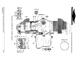
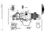
Refer to Figure 10-61; loosen and remove cylinder drain tubes (45).
4.
Remove and discard the drain tube seals (46).
5.
Remove the drain tube fittings (16).
6.
While removing an engine cylinder, inspect components for wear and conformance to
dimensional criteria. Replace any component based on the following:
a.
Only parts that meet
service limits
may remain in service or be re-used.
b.
If a part fails to meet a service limit tolerance, replace it with a part that meets the
specified service limits.
7.
Remove the bolts (61), washers (62), baffle support (63), lower baffles (66), and
baffle base (67).
8.
Remove and inspect the springs (68).
9.
Remove the CHT Sensor according to instructions in Section 10-6.21.
10.
Remove the Fuel Injection Solenoid and the Fuel Injector from the cylinder according
to instructions in Section 10-6.10.
11.
Remove the Valve Train according to instructions in Section 10-8.3.
12.
Remove the hydraulic tappets and pushrod tubes according to instructions in Section
10-8.11.
13.
Using the appropriate wrenches, carefully remove flange nuts (41, 42, and 49) from
the cylinder base flange and seventh stud locations.
14.
As the last pieces of fastening hardware are removed, cradle the cylinder in your arm
to support the cylinder.
15.
Remove the 7
th
stud brackets (47 and 48).
CAUTION: The piston will be damaged if allowed to drop as the
cylinder is withdrawn.
16.
While supporting the cylinder, carefully and slowly pull the cylinder outward in a
straight plane with one hand, keeping the other hand free to catch the piston as the
cylinder is withdrawn to prevent damage to the crankcase or cylinder.
17.
Remove the cylinder base O-ring (52). Install the old O-ring in a figure 8 (Figure 10-
60) pattern to support the connecting rod.

