Maintenance Inspections
Teledyne Continental Motors, Inc.
TM
8.
Replace the cover (98) and secure with screws (103), new lock washer (104), and
washer (26); torque per Appendix B.
9.
Connect the vapor return line to the orifice fitting (114); torque according to
Appendix B.
10.
Reconnect the fuel pressure sensors; verify connectors lock in place (check for pins
visible in observation ports).
7-3.14.2. Fuel Filter Service
Engine fuel filters vary by engine model. Select the procedure which matches the engine
undergoing inspection.
7-3.14.2.1. IOF-550-B and C Inline Fuel Filter Service
The inline fuel filter assembly is enclosed in one piece housing. The filter element cannot
be removed from the housing without damage; clean the assembly as one unit.
Procedure
1.
Remove the cushion clamps securing the inline filter and remove the filter assembly
from the engine. Cap the fuel lines to prevent contamination.
2.
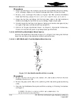
Remove the fitting and O-ring from the filter (Figure 7-25). Discard the O-ring.
3.
Clean the filter according to the “Cleaning” instructions in Chapter 9.
CAUTION: The filter is very sensitive to debris and contamination;
Use only fresh solvent to clean the filter.
4.
Repeat flushing until no debris is present on the clean, white paper filter.
5.
If the fuel filter/housing unit cannot be thoroughly cleaned, replace the filter
element/housing unit as one component.
6.
Visually inspect hardware threads and sealing surfaces for wear or rough surfaces.
Replace worn or rough hardware.
7.
Install a new O-ring and the straight fitting into the filter. Torque the fitting per
Appendix B.
8.
Connect the fuel filter to the fuel lines; torque the fitting “B” nuts per Appendix B.
Figure 7-25.
Inline Fuel Filter Assembly
9.
Secure the fuel filter to the engine with cushion clamps, bolts, washers, and new lock
nuts. Torque the fasteners according to Appendix B.
7-40
IOF-550 Permold Series Engine Maintenance Manual
1 April 2007


