Protective Elements
694
MCDLV4
DOK-HB-MCDLV4-2E
name.TripCmd
name.Alarm L1
name.Alarm L2
name.Alarm L3
name.Trip
IH2.Blo L1
IH2.Blo L2
IH2.Blo L3
Please Refer To Diagram: Blockings
51V Pickup =
%Pickup * 51P
I>
IL1
IL2
IL3
name.Trip L1
name.Trip L2
name.Alarm
Please Refer To Diagram:
Trip blockings
inactive
active
name.IH2 Blo
(Stage is not deactivated and no active blocking signals )
name.IH2 Blo*
ILx max
(Tripping command deactivated or blocked . )
5
6
7
4
3
Please Refer To Diagram: IH2*
Please Refer To Diagram: IH2*
Please Refer To Diagram: IH2*
15a
16b
17b
18b
24b
25b
26b
14
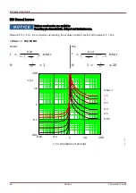
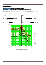
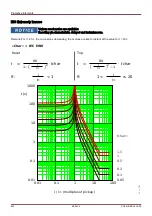
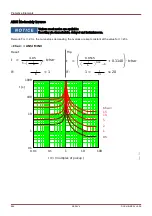
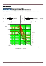
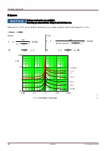
INV
ILx max
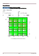
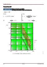
name.t-reset delay
name.tchar
name.Char
name.Reset Mode
Based on above parameters ,
tripping times and reset modes will
be calculated by the device .
I[1]...[n]
name =
I[1]...[n]
*=
A
pp
lie
s o
nly
to
d
ev
ic
es
th
a
t o
ffe
r I
n
ru
sh
P
ro
te
c
tio
n
name.Trip L3
VL1
VL2
VL3
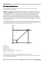
Pickup%
25%
100%
V
25%
VRestraint max
%Pickup
&
&
&
&
&
&
&
&
&
&
>1
>1
Fundamental
True RMS
name.Measuring
method
Phase to Ground
name.Measuring Mode
Phase to Phase
38b 38c
38a
inactive
name.Meas Circuit
Superv
active
&
15
name.* I[1]...[n] Fault in projected direction
9
Please Refer To Diagram: direction decision phase overcurrent***
&
**
*=
A
p
pli
e
s o
n
ly
to
d
e
vic
es
th
a
t o
ffe
r D
ire
ct
io
n
a
l F
ea
tu
re
.
Summary of Contents for HighPROtec MCDLV4
Page 3: ...Order Code Order Code 3 MCDLV4 DOK HB MCDLV4 2E...
Page 47: ...Installation and Connection 47 MCDLV4 DOK HB MCDLV4 2E...
Page 164: ...Input Output and LED Settings 164 MCDLV4 DOK HB MCDLV4 2E...
Page 433: ...Parameters 433 MCDLV4 DOK HB MCDLV4 2E...
Page 457: ...Device Parameters 457 MCDLV4 DOK HB MCDLV4 2E...
Page 473: ...Blockings 473 MCDLV4 DOK HB MCDLV4 2E...
Page 988: ...Protective Elements 988 MCDLV4 DOK HB MCDLV4 2E P P Q P Q P Q Q Q P S S...
Page 989: ...Protective Elements 989 MCDLV4 DOK HB MCDLV4 2E Pr Q P Q P Qr...
Page 1023: ...Protective Elements 1023 MCDLV4 DOK HB MCDLV4 2E...


