


Communication Protocols
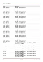
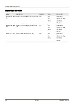
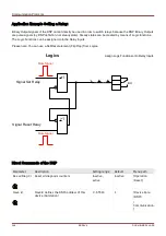
Application Example Setting a Relay:
Binary Output signals of the DNP cannot directly be used in order to switch relays because the DNP Binary Outputs
are pulse signals (by DNP definition, not steady state). Steady states can be created by means of Logic functions.
The Logic Functions can be assigned onto the Relay Inputs.
Please note: You can use a Set/Reset element (Flip Flop) from Logics.
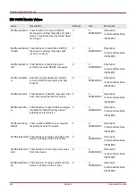
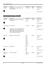
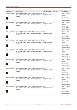
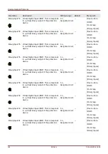
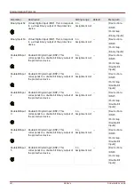
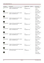
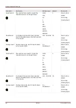
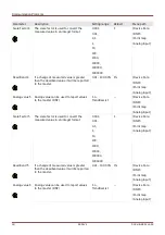
Direct Commands of the DNP
Parameter
Description
Setting range
Default
Menu path
Res all Diag Cr
Reset all diagnosis counters
inactive,
active
inactive
[Operation
/Reset]
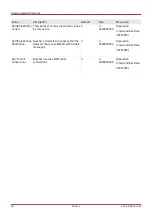
Slave Id
SlaveId defines the DNP3 address of this
device (Outstation)
0 - 65519
1
[Device Para
/DNP3
/
Communication
]
346
MCDLV4
DOK-HB-MCDLV4-2E
BO
Signal Set Relay
Signal Reset Relay
Pulse Signal
Pulse Signal
Logics
Assign Logic Functions onto Relay Inputs
>1
>1
Summary of Contents for HighPROtec MCDLV4
Page 3: ...Order Code Order Code 3 MCDLV4 DOK HB MCDLV4 2E...
Page 47: ...Installation and Connection 47 MCDLV4 DOK HB MCDLV4 2E...
Page 164: ...Input Output and LED Settings 164 MCDLV4 DOK HB MCDLV4 2E...
Page 433: ...Parameters 433 MCDLV4 DOK HB MCDLV4 2E...
Page 457: ...Device Parameters 457 MCDLV4 DOK HB MCDLV4 2E...
Page 473: ...Blockings 473 MCDLV4 DOK HB MCDLV4 2E...
Page 988: ...Protective Elements 988 MCDLV4 DOK HB MCDLV4 2E P P Q P Q P Q Q Q P S S...
Page 989: ...Protective Elements 989 MCDLV4 DOK HB MCDLV4 2E Pr Q P Q P Qr...
Page 1023: ...Protective Elements 1023 MCDLV4 DOK HB MCDLV4 2E...