General Lists
Name
Description
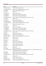
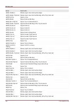
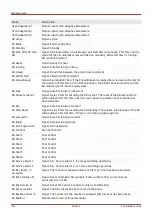
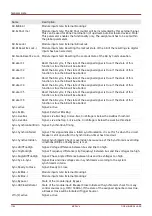
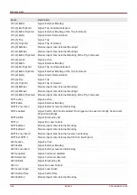
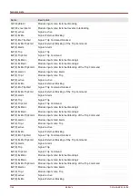
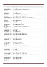
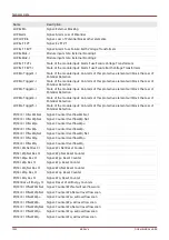
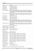
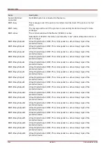
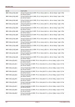
ReCon[2].Release
Energy Resource
Signal: Release Energy Resource.
ReCon[2].ExBlo1-I
Module input state: External blocking1
ReCon[2].ExBlo2-I
Module input state: External blocking2
ReCon[2].V Ext Release
PCC-I
Module input state: Release signal is being generated by the PCC (External Release)
ReCon[2].PCC Fuse Fail
VT-I
State of the module input: Blocking if the fuse of a voltage transformer has tripped at
the PCC.
ReCon[2].reconnected-I
This signal indicates the state "reconnected" (mains parallel).
ReCon[2].Decoupling1-I Decoupling function, that blocks the reconnection.
ReCon[2].Decoupling2-I Decoupling function, that blocks the reconnection.
ReCon[2].Decoupling3-I Decoupling function, that blocks the reconnection.
ReCon[2].Decoupling4-I Decoupling function, that blocks the reconnection.
ReCon[2].Decoupling5-I Decoupling function, that blocks the reconnection.
ReCon[2].Decoupling6-I Decoupling function, that blocks the reconnection.
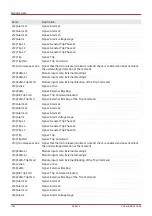
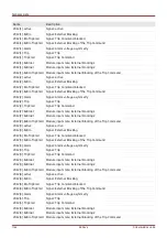
UFLS.active
Signal: active
UFLS.ExBlo
Signal: External Blocking
UFLS.Fuse Fail VT Blo
Signal: Blocked by Fuse Failure (VT)
UFLS.I1 Release
Signal: "I Minimum Current" in order to prevent faulty tripping. Module will be
released if the current exceeds this value.
UFLS.VLL min
Signal: Minimum Voltage
UFLS.Power Angle
Signal: Trigger Phi-Power (Positive Phase Sequence System)
UFLS.P min
Signal: Minimum Value (threshold) for the Active Power
UFLS.P Blo
Loadshedding
Signal: Load shedding blocked based on evaluation of active power
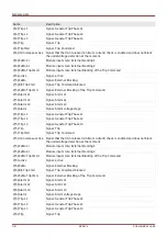
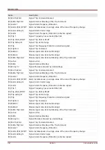
UFLS.f<
Signal: Underfrequency threshold
UFLS.Alarm
Signal: Alarm P->&f<
UFLS.Trip
Signal: Signal: Trip
UFLS.DefaultSet
Signal: Default Parameter Set
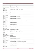
UFLS.AdaptSet 1
Signal: Adaptive Parameter 1
UFLS.AdaptSet 2
Signal: Adaptive Parameter 2
UFLS.AdaptSet 3
Signal: Adaptive Parameter 3
UFLS.AdaptSet 4
Signal: Adaptive Parameter 4
UFLS.AdaptSet 5
Signal: Adaptive Parameter 5
UFLS.ExBlo1-I
Module input state: External blocking1
UFLS.ExBlo2-I
Module input state: External blocking2
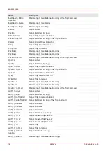
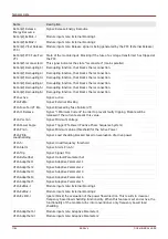
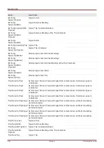
UFLS.Ex Pdir-I
Ignore (block) the evaluation of the power flow direction. This results in classical
frequency based load shedding functionallity. When this feature is set and active, the
functionallity of the module turns into conventional, only frequency based load
shedding.
UFLS.AdaptSet1-I
Module input state: Adaptive Parameter1
UFLS.AdaptSet2-I
Module input state: Adaptive Parameter2
1192
MCDLV4
DOK-HB-MCDLV4-2E
Summary of Contents for HighPROtec MCDLV4
Page 3: ...Order Code Order Code 3 MCDLV4 DOK HB MCDLV4 2E...
Page 47: ...Installation and Connection 47 MCDLV4 DOK HB MCDLV4 2E...
Page 164: ...Input Output and LED Settings 164 MCDLV4 DOK HB MCDLV4 2E...
Page 433: ...Parameters 433 MCDLV4 DOK HB MCDLV4 2E...
Page 457: ...Device Parameters 457 MCDLV4 DOK HB MCDLV4 2E...
Page 473: ...Blockings 473 MCDLV4 DOK HB MCDLV4 2E...
Page 988: ...Protective Elements 988 MCDLV4 DOK HB MCDLV4 2E P P Q P Q P Q Q Q P S S...
Page 989: ...Protective Elements 989 MCDLV4 DOK HB MCDLV4 2E Pr Q P Q P Qr...
Page 1023: ...Protective Elements 1023 MCDLV4 DOK HB MCDLV4 2E...


