


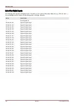

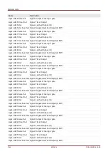
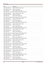
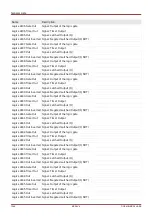
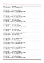


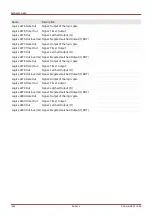


General Lists
Name
Description
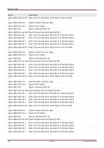
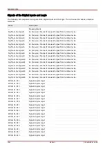
DNP3.BinaryOutput20
Virtual Digital Output (DNP). This corresponds to a virtual binary input of the
protective device.
DNP3.BinaryOutput21
Virtual Digital Output (DNP). This corresponds to a virtual binary input of the
protective device.
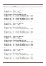
DNP3.BinaryOutput22
Virtual Digital Output (DNP). This corresponds to a virtual binary input of the
protective device.
DNP3.BinaryOutput23
Virtual Digital Output (DNP). This corresponds to a virtual binary input of the
protective device.
DNP3.BinaryOutput24
Virtual Digital Output (DNP). This corresponds to a virtual binary input of the
protective device.
DNP3.BinaryOutput25
Virtual Digital Output (DNP). This corresponds to a virtual binary input of the
protective device.
DNP3.BinaryOutput26
Virtual Digital Output (DNP). This corresponds to a virtual binary input of the
protective device.
DNP3.BinaryOutput27
Virtual Digital Output (DNP). This corresponds to a virtual binary input of the
protective device.
DNP3.BinaryOutput28
Virtual Digital Output (DNP). This corresponds to a virtual binary input of the
protective device.
DNP3.BinaryOutput29
Virtual Digital Output (DNP). This corresponds to a virtual binary input of the
protective device.
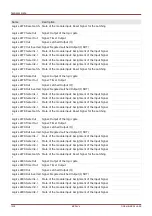
DNP3.BinaryOutput30
Virtual Digital Output (DNP). This corresponds to a virtual binary input of the
protective device.
DNP3.BinaryOutput31
Virtual Digital Output (DNP). This corresponds to a virtual binary input of the
protective device.
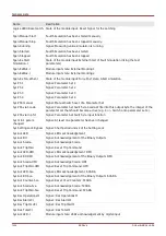
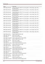
Logics.LE1.Gate Out
Signal: Output of the logic gate
Logics.LE1.Timer Out
Signal: Timer Output
Logics.LE1.Out
Signal: Latched Output (Q)
Logics.LE1.Out inverted
Signal: Negated Latched Output (Q NOT)
Logics.LE2.Gate Out
Signal: Output of the logic gate
Logics.LE2.Timer Out
Signal: Timer Output
Logics.LE2.Out
Signal: Latched Output (Q)
Logics.LE2.Out inverted
Signal: Negated Latched Output (Q NOT)
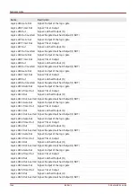
Logics.LE3.Gate Out
Signal: Output of the logic gate
Logics.LE3.Timer Out
Signal: Timer Output
Logics.LE3.Out
Signal: Latched Output (Q)
Logics.LE3.Out inverted
Signal: Negated Latched Output (Q NOT)
Logics.LE4.Gate Out
Signal: Output of the logic gate
Logics.LE4.Timer Out
Signal: Timer Output
Logics.LE4.Out
Signal: Latched Output (Q)
Logics.LE4.Out inverted
Signal: Negated Latched Output (Q NOT)
Logics.LE5.Gate Out
Signal: Output of the logic gate
Logics.LE5.Timer Out
Signal: Timer Output
Logics.LE5.Out
Signal: Latched Output (Q)
Logics.LE5.Out inverted
Signal: Negated Latched Output (Q NOT)
1244
MCDLV4
DOK-HB-MCDLV4-2E
Summary of Contents for HighPROtec MCDLV4
Page 3: ...Order Code Order Code 3 MCDLV4 DOK HB MCDLV4 2E...
Page 47: ...Installation and Connection 47 MCDLV4 DOK HB MCDLV4 2E...
Page 164: ...Input Output and LED Settings 164 MCDLV4 DOK HB MCDLV4 2E...
Page 433: ...Parameters 433 MCDLV4 DOK HB MCDLV4 2E...
Page 457: ...Device Parameters 457 MCDLV4 DOK HB MCDLV4 2E...
Page 473: ...Blockings 473 MCDLV4 DOK HB MCDLV4 2E...
Page 988: ...Protective Elements 988 MCDLV4 DOK HB MCDLV4 2E P P Q P Q P Q Q Q P S S...
Page 989: ...Protective Elements 989 MCDLV4 DOK HB MCDLV4 2E Pr Q P Q P Qr...
Page 1023: ...Protective Elements 1023 MCDLV4 DOK HB MCDLV4 2E...