General Lists
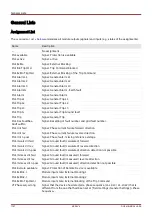
Name
Description
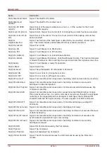
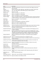
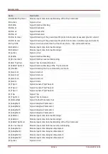
SG[1].ON incl Prot ON
Signal: The ON Command includes the ON Command issued by the Protection
module.
SG[1].OFF incl TripCmd
Signal: The OFF Command includes the OFF Command issued by the Protection
module.
SG[1].Position Ind
manipul
Signal: Position Indicators faked
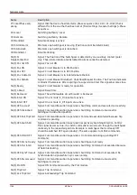
SG[1].SGwear Slow SG
Signal: Alarm, the circuit breaker (load-break switch) becomes slower
SG[1].Res SGwear Sl SG Signal: Resetting the slow Switchgear Alarm
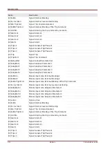
SG[1].ON Cmd
Signal: ON Command issued to the switchgear. Depending on the setting the signal
may include the ON command of the Prot module.
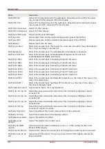
SG[1].OFF Cmd
Signal: OFF Command issued to the switchgear. Depending on the setting the signal
may include the OFF command of the Prot module.
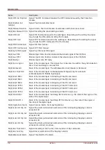
SG[1].ON Cmd manual
Signal: ON Cmd manual
SG[1].OFF Cmd manual
Signal: OFF Cmd manual
SG[1].Sync ON request
Signal: Synchronous ON request
SG[1].Aux ON-I
Module Input State: Position indicator/check-back signal of the CB (52a)
SG[1].Aux OFF-I
Module input state: Position indicator/check-back signal of the CB (52b)
SG[1].Ready-I
Module input state: CB ready
SG[1].Sys-in-Sync-I
State of the module input: This signals has to become true within the synchronization
time. If not, switching is unsuccessful.
SG[1].Removed-I
State of the module input: The withdrawable circuit breaker is Removed
SG[1].Ack TripCmd-I
State of the module input: Acknowledgement Signal (only for automatic
acknowledgement) Module input signal
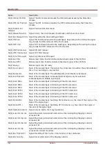
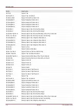
SG[1].Interl ON1-I
State of the module input: Interlocking of the ON command
SG[1].Interl ON2-I
State of the module input: Interlocking of the ON command
SG[1].Interl ON3-I
State of the module input: Interlocking of the ON command
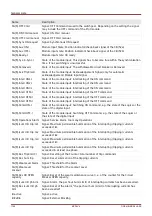
SG[1].Interl OFF1-I
State of the module input: Interlocking of the OFF command
SG[1].Interl OFF2-I
State of the module input: Interlocking of the OFF command
SG[1].Interl OFF3-I
State of the module input: Interlocking of the OFF command
SG[1].SCmd ON-I
State of the module input: Switching ON Command, e.g. the state of the Logics or the
state of the digital input
SG[1].SCmd OFF-I
State of the module input: Switching OFF Command, e.g. the state of the Logics or
the state of the digital input
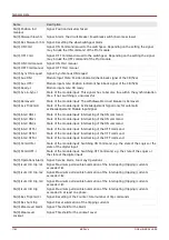
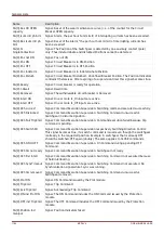
SG[1].Operations Alarm Signal: Service Alarm, too many Operations
SG[1].Isum Intr trip: IL1
Signal: Maximum permissible Summation of the interrupting (tripping) currents
exceeded: IL1
SG[1].Isum Intr trip: IL2
Signal: Maximum permissible Summation of the interrupting (tripping) currents
exceeded: IL2
SG[1].Isum Intr trip: IL3
Signal: Maximum permissible Summation of the interrupting (tripping) currents
exceeded: IL3
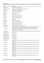
SG[1].Isum Intr trip
Signal: Maximum permissible Summation of the interrupting (tripping) currents
exceeded in at least one phase.
SG[1].Res TripCmd Cr
Signal: Resetting of the Counter: total number of trip commands
SG[1].Res Sum trip
Signal: Reset summation of the tripping currents
1159
MCDLV4
DOK-HB-MCDLV4-2E
Summary of Contents for HighPROtec MCDLV4
Page 3: ...Order Code Order Code 3 MCDLV4 DOK HB MCDLV4 2E...
Page 47: ...Installation and Connection 47 MCDLV4 DOK HB MCDLV4 2E...
Page 164: ...Input Output and LED Settings 164 MCDLV4 DOK HB MCDLV4 2E...
Page 433: ...Parameters 433 MCDLV4 DOK HB MCDLV4 2E...
Page 457: ...Device Parameters 457 MCDLV4 DOK HB MCDLV4 2E...
Page 473: ...Blockings 473 MCDLV4 DOK HB MCDLV4 2E...
Page 988: ...Protective Elements 988 MCDLV4 DOK HB MCDLV4 2E P P Q P Q P Q Q Q P S S...
Page 989: ...Protective Elements 989 MCDLV4 DOK HB MCDLV4 2E Pr Q P Q P Qr...
Page 1023: ...Protective Elements 1023 MCDLV4 DOK HB MCDLV4 2E...

