


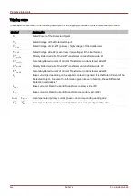
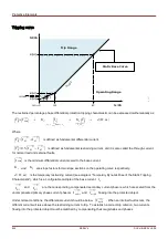


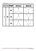
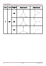
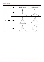

Protective Elements
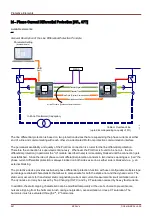
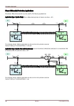
ANSI 87L / 87T – Line Differential Protection
with an In-Zone transformer
Note 1: For both protective devices the current input X3 must be
connected, and furthermore, the fiber optics must be connected
with each other's X102, and the “ProtCom” protection interface must
be configured.
In general the following parameters should be set to the same
values for both devices.
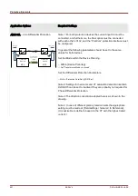
Set the Mode within the Device Planning.
⇨
In the menu [Device Planning]
⇨ S
et “Transformer.Mode = use”
Set the Field Parameters of the Transformer.
⇨
In the menu [Field Para\Transformer]
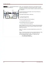
Set the Differential Protection Parameters.
⇨
In the menu [Protection Para\Set [x]\Diff-Prot]
Note 2: Settings for harmonic and CT saturation detection like Stab
H2/H4/H5 can be set to active if they are probably used for Phase
Differential Protection.
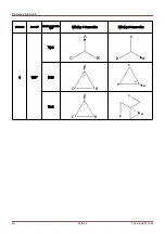
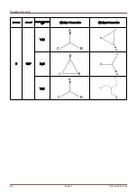
Note 3: The direction convention adopted here is as shown in the
drawing.
Note 4: In the device settings it must be defined at which side of the
transformer the measuring is done. The actual side can be
selected at [Field settings / Transformer / Measuring side]:
•
W1 (primary winding side)
•
W2 (secondary winding side)
602
MCDLV4
DOK-HB-MCDLV4-2E
Id
_Z
0
3
3
3
Protective
Device
87L
Protective
Device
87L
Protection
communi-
cation
interface
I
I
In Zone
Trans-
former
( free
option)
W2 W1
(local)
(remote)
Summary of Contents for HighPROtec MCDLV4
Page 3: ...Order Code Order Code 3 MCDLV4 DOK HB MCDLV4 2E...
Page 47: ...Installation and Connection 47 MCDLV4 DOK HB MCDLV4 2E...
Page 164: ...Input Output and LED Settings 164 MCDLV4 DOK HB MCDLV4 2E...
Page 433: ...Parameters 433 MCDLV4 DOK HB MCDLV4 2E...
Page 457: ...Device Parameters 457 MCDLV4 DOK HB MCDLV4 2E...
Page 473: ...Blockings 473 MCDLV4 DOK HB MCDLV4 2E...
Page 988: ...Protective Elements 988 MCDLV4 DOK HB MCDLV4 2E P P Q P Q P Q Q Q P S S...
Page 989: ...Protective Elements 989 MCDLV4 DOK HB MCDLV4 2E Pr Q P Q P Qr...
Page 1023: ...Protective Elements 1023 MCDLV4 DOK HB MCDLV4 2E...