


Recorders
Behaviour of the Fault Recorder
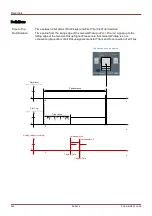
Who triggers the Fault Recorder?
The
Fault Recorder will be triggered by the rising edge of the »P
ROT
.P
ICKUP
« (General Pickup) signal.
Please note
that »
P
ROT
.P
ICKUP
«
(General Pickup) is an or-connection of all Pickup signals. The first Pickup will trigger the Fault
recorder.
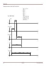
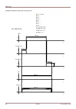
At which point of time will the fault measurements be captured?
The fault measurements will be captured (written) when the trip decision is taken. The point in time, when the
measurements are captured (after a trip) can be delayed optionally by the parameter »
t-meas-delay«. This might be
reasonable in order to achieve more reliable measuring values (e.g. in order to avoid measuring disturbances
caused by significant DC-components).
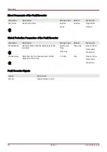
Modes
In case of a fault record should be written even if an general alarm has not lead to a trip, the parameter »
Record-
Mode« is to be set to »Alarms and Trips« .
Set parameter »
Record-Mode« to »Trips only«, if an Alarm that is not followed by a trip decision should not lead to a
trip.
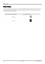
When does the overlay (popup) appears on the display of the HMI?
A popup will appear on the HMI display, when the General Pickup (Prot.Pickup) disappears.
No time to trip will be shown if the pickup signal that triggers the fault recorder is
issued by another protection module than the trip signal. This might happen if
more than one protection module is involved into a fault.
Please note: The parameter settings (thresholds etc.) that are shown in a fault record
are not part of the fault record itself. They are always read out from the current device
setting. If parameters settings that are shown in a fault record could have been
updated, they will be indicated with an asterisk symbol within the fault record.
To prevent this please proceed as follows:
Save any fault record that should be archived to your local network/hard disk before
doing any parameter change. Delete all the fault records in your fault recorder
afterwards.
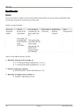
Memory
The last stored fault record is saved (fail-safe) within the
Fault Recorder (the others are saved within a memory that
depends on the auxiliary power of the protective relay). If there is no more memory free, the oldest record will be
overwritten (FIFO). Up to 20 records can be stored.
269
MCDLV4
DOK-HB-MCDLV4-2E
Summary of Contents for HighPROtec MCDLV4
Page 3: ...Order Code Order Code 3 MCDLV4 DOK HB MCDLV4 2E...
Page 47: ...Installation and Connection 47 MCDLV4 DOK HB MCDLV4 2E...
Page 164: ...Input Output and LED Settings 164 MCDLV4 DOK HB MCDLV4 2E...
Page 433: ...Parameters 433 MCDLV4 DOK HB MCDLV4 2E...
Page 457: ...Device Parameters 457 MCDLV4 DOK HB MCDLV4 2E...
Page 473: ...Blockings 473 MCDLV4 DOK HB MCDLV4 2E...
Page 988: ...Protective Elements 988 MCDLV4 DOK HB MCDLV4 2E P P Q P Q P Q Q Q P S S...
Page 989: ...Protective Elements 989 MCDLV4 DOK HB MCDLV4 2E Pr Q P Q P Qr...
Page 1023: ...Protective Elements 1023 MCDLV4 DOK HB MCDLV4 2E...