⎯
72
⎯
6 F 2 S 0 8 4 6
2.4.7 Switch-Onto-Fault
Protection
In order to quickly remove a fault which may occur when a faulted line or busbar is energized, the
switch-onto-fault (SOTF) protection functions for a certain period after the circuit breaker is
closed.
The SOTF protection is performed by a non-directional overcurrent element and distance
measuring elements. The overcurrent protection is effective in detecting close-up three-phase
faults on the line in particular when the voltage transformer is installed on the line side. This is
because the voltage input to the distance measuring elements is absent continuously before and
after the fault, and thus it is difficult for the distance measuring elements to detect the fault.
The distance measuring elements can operate for faults other than close-up three-phase faults. One
of the zone 1 to zone ND elements can be used for the SOTF protection.
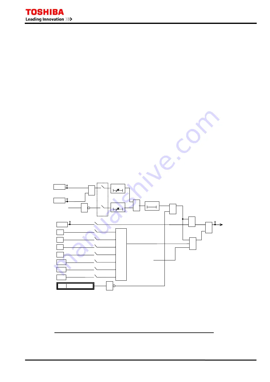
Scheme logic
The scheme logic for the SOTF protection is shown in Figure 2.4.7.1. The SOTF protection issues
a three-phase tripping signal M-TRIP for the operation of an overcurrent element OCH or distance
measuring elements Z1 to ZND for 500 ms after the circuit breaker is closed (CB-OR = 1) and/or
for 500ms after the undervoltage dead line detector resets. The method of controlling the SOTF
protection by CB closing and/or by undervoltage dead line detection is selected by scheme switch
[SOTF-DL]. Elements UVFS and UVLG provide undervoltage dead line detection.
Tripping by each element can be disabled by the scheme switches [SOTF-OC] to [SOTF-ZND].
When a VT failure is detected (NON VTF = 0), tripping by the distance measuring elements is
blocked.
≥
1
&
&
≥
1
1
0.5s
0 t
SOTF-TRIP
[SOTF-Z1]
[SOTF-OC]
NON VTF
CB-OR
OCH
Z1
"ON"
"ON"
Z2
"ON"
Z3
"ON"
0 - 300s
t 0
TSOTF
UVLS
≥
1
0 - 300s
t 0
TSOTF
"UV",
"Both"
"CB",
"Both"
[SOTF-DL]
[SOTF-Z2]
[SOTF-Z3]
[SOTF-F]
ZF
"ON"
ZR1
"ON"
ZR2
"ON"
ZND
"ON"
[SOTF-R1]
[SOTF-R2]
[SOTF-ND]
&
55: OCH-A
56: OCH-B
57: OCH-C
UVLG
78:UVLG-A
79:UVLG-B
80:UVLG-C
72:UVLS-AB
73:UVLS-BC
74:UVLS-CA
&
SOTF_BLOCK
1623
1
183
Figure 2.4.7.1 SOTF Scheme Logic
Setting
The setting elements necessary for the SOTF protection and their setting ranges are as follows:
Element Range
Step Default Remarks
OCH
2.0 - 15.0 A
0.1 A
6.0 A
Overcurrent setting
( 0.4 - 3.0 A
0.1 A
1.2 A) (*)
TSOTF
0 – 300 s
1 s
5 s
SOTF check timer
Summary of Contents for GRZ100 B Series
Page 264: ... 263 6 F 2 S 0 8 4 6 Appendix A Block Diagram ...
Page 271: ... 270 6 F 2 S 0 8 4 6 ...
Page 272: ... 271 6 F 2 S 0 8 4 6 Appendix B Signal List ...
Page 307: ... 306 6 F 2 S 0 8 4 6 ...
Page 308: ... 307 6 F 2 S 0 8 4 6 Appendix C Variable Timer List ...
Page 310: ... 309 6 F 2 S 0 8 4 6 Appendix D Binary Input Output Default Setting List ...
Page 321: ... 320 6 F 2 S 0 8 4 6 ...
Page 322: ... 321 6 F 2 S 0 8 4 6 Appendix E Details of Relay Menu and LCD Button Operation ...
Page 331: ... 330 6 F 2 S 0 8 4 6 ...
Page 340: ... 339 6 F 2 S 0 8 4 6 Appendix G Typical External Connections ...
Page 377: ... 376 6 F 2 S 0 8 4 6 ...
Page 384: ... 383 6 F 2 S 0 8 4 6 Appendix J Return Repair Form ...
Page 388: ... 387 6 F 2 S 0 8 4 6 Customer Name Company Name Address Telephone No Facsimile No Signature ...
Page 389: ... 388 6 F 2 S 0 8 4 6 ...
Page 390: ... 389 6 F 2 S 0 8 4 6 Appendix K Technical Data ...
Page 401: ... 400 6 F 2 S 0 8 4 6 ...
Page 402: ... 401 6 F 2 S 0 8 4 6 Appendix L Symbols Used in Scheme Logic ...
Page 405: ... 404 6 F 2 S 0 8 4 6 ...
Page 406: ... 405 6 F 2 S 0 8 4 6 Appendix M Example of Setting Calculation ...
Page 417: ... 416 6 F 2 S 0 8 4 6 ...
Page 418: ... 417 6 F 2 S 0 8 4 6 Appendix N IEC60870 5 103 Interoperability and Troubleshooting ...
Page 434: ... 433 6 F 2 S 0 8 4 6 Appendix P Inverse Time Characteristics ...
Page 437: ... 436 6 F 2 S 0 8 4 6 ...
Page 438: ... 437 6 F 2 S 0 8 4 6 Appendix Q Failed Module Tracing and Replacement ...
Page 444: ... 443 6 F 2 S 0 8 4 6 Appendix R Ordering ...
Page 447: ......


