⎯
112
⎯
6 F 2 S 0 8 4 6
Very Inverse
t = T
×
13.5
(I/Is)
−
1
Extremely Inverse
t = T
×
80
(I/Is)
2
−
1
where,
t = operating time
I = fault current
Is = current setting
T = time multiplier setting
Definite time reset
The definite time resetting characteristic is provided.
If the delay period is set to instantaneous (TOCIR, TEFIR, TDEFR or TDERR=0.0s), then no
intentional delay is added. As soon as the energising current falls below the reset threshold, the
element returns to its reset condition.
If the delay period is set to some value in seconds, then an intentional delay is added to the reset
period. If the energising current exceeds the setting for a transient period without causing tripping,
then resetting is delayed for a user-definable period. When the energising current falls below the
reset threshold, the integral state (the point towards operation that it has travelled) of the timing
function (IDMT) is held for that period.
This does not apply following a trip operation, in which case resetting is always instantaneous.
2.5.5 Out-of-Step Element OST
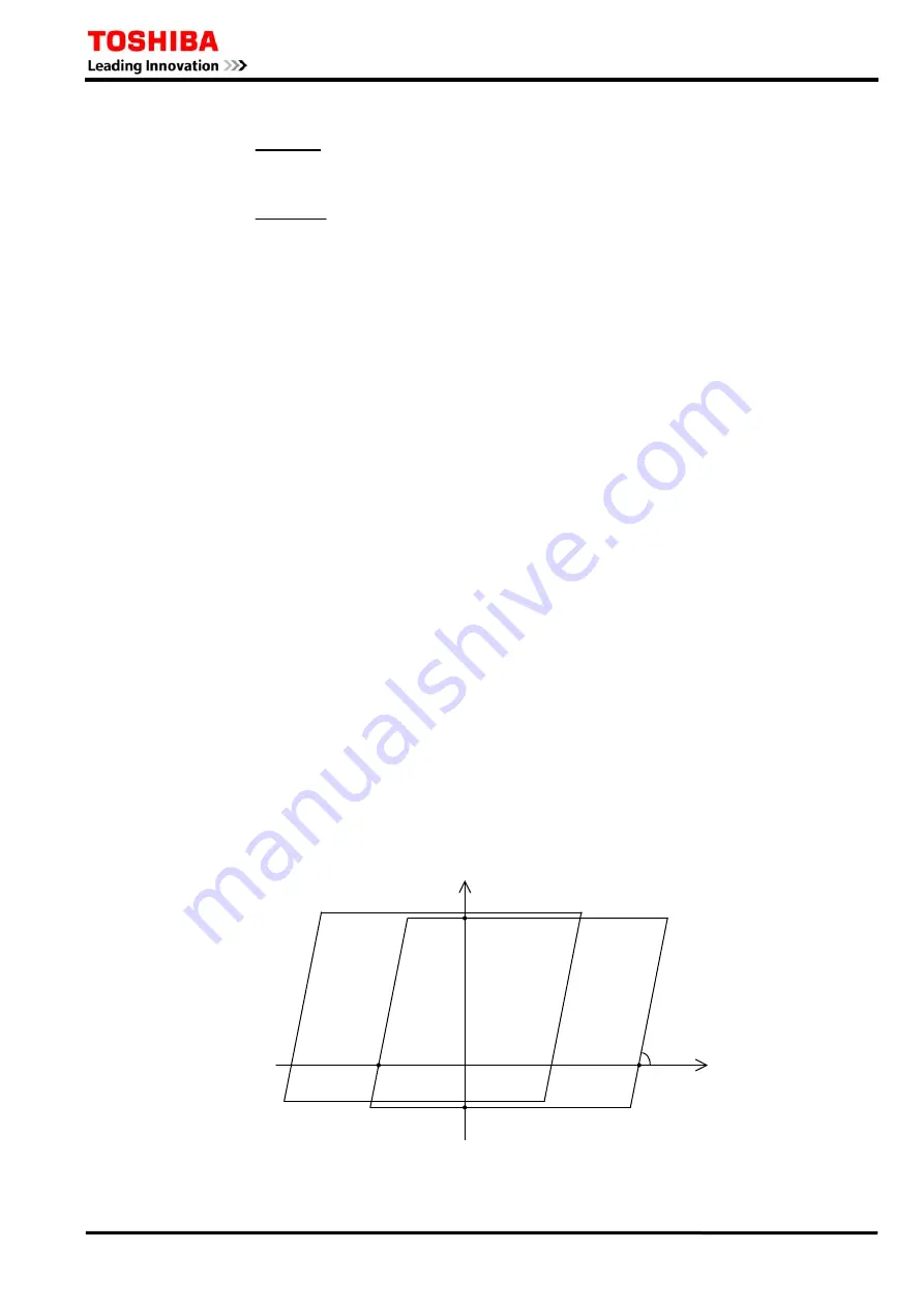
The out-of-step element used for out-of-step tripping contains two impedance measuring elements
with quadrilateral characteristics, ZM and ZN. Figure 2.5.5.1 shows their characteristics. The
quadrilateral characteristic of ZM is formed by the reactance lines parallel to the R-axis and the
ohm lines with a leading angle of 75
°
to the R-axis.
The characteristics of ZN can be obtained by shifting ZM in the
−
R-axis direction by
(OSTR1-OSTR2).
R
75
°
X
ZN C
B
A ZM
OSTR1
−
OSTR2
−
OSTXB
OSTXF
Figure 2.5.5.1 Out-of-Step Element
Summary of Contents for GRZ100 B Series
Page 264: ... 263 6 F 2 S 0 8 4 6 Appendix A Block Diagram ...
Page 271: ... 270 6 F 2 S 0 8 4 6 ...
Page 272: ... 271 6 F 2 S 0 8 4 6 Appendix B Signal List ...
Page 307: ... 306 6 F 2 S 0 8 4 6 ...
Page 308: ... 307 6 F 2 S 0 8 4 6 Appendix C Variable Timer List ...
Page 310: ... 309 6 F 2 S 0 8 4 6 Appendix D Binary Input Output Default Setting List ...
Page 321: ... 320 6 F 2 S 0 8 4 6 ...
Page 322: ... 321 6 F 2 S 0 8 4 6 Appendix E Details of Relay Menu and LCD Button Operation ...
Page 331: ... 330 6 F 2 S 0 8 4 6 ...
Page 340: ... 339 6 F 2 S 0 8 4 6 Appendix G Typical External Connections ...
Page 377: ... 376 6 F 2 S 0 8 4 6 ...
Page 384: ... 383 6 F 2 S 0 8 4 6 Appendix J Return Repair Form ...
Page 388: ... 387 6 F 2 S 0 8 4 6 Customer Name Company Name Address Telephone No Facsimile No Signature ...
Page 389: ... 388 6 F 2 S 0 8 4 6 ...
Page 390: ... 389 6 F 2 S 0 8 4 6 Appendix K Technical Data ...
Page 401: ... 400 6 F 2 S 0 8 4 6 ...
Page 402: ... 401 6 F 2 S 0 8 4 6 Appendix L Symbols Used in Scheme Logic ...
Page 405: ... 404 6 F 2 S 0 8 4 6 ...
Page 406: ... 405 6 F 2 S 0 8 4 6 Appendix M Example of Setting Calculation ...
Page 417: ... 416 6 F 2 S 0 8 4 6 ...
Page 418: ... 417 6 F 2 S 0 8 4 6 Appendix N IEC60870 5 103 Interoperability and Troubleshooting ...
Page 434: ... 433 6 F 2 S 0 8 4 6 Appendix P Inverse Time Characteristics ...
Page 437: ... 436 6 F 2 S 0 8 4 6 ...
Page 438: ... 437 6 F 2 S 0 8 4 6 Appendix Q Failed Module Tracing and Replacement ...
Page 444: ... 443 6 F 2 S 0 8 4 6 Appendix R Ordering ...
Page 447: ......


