


Part Names and Functions
FQ2 User’s Manual
2
In
sta
llatio
n
a
nd
Con
nection
s
31
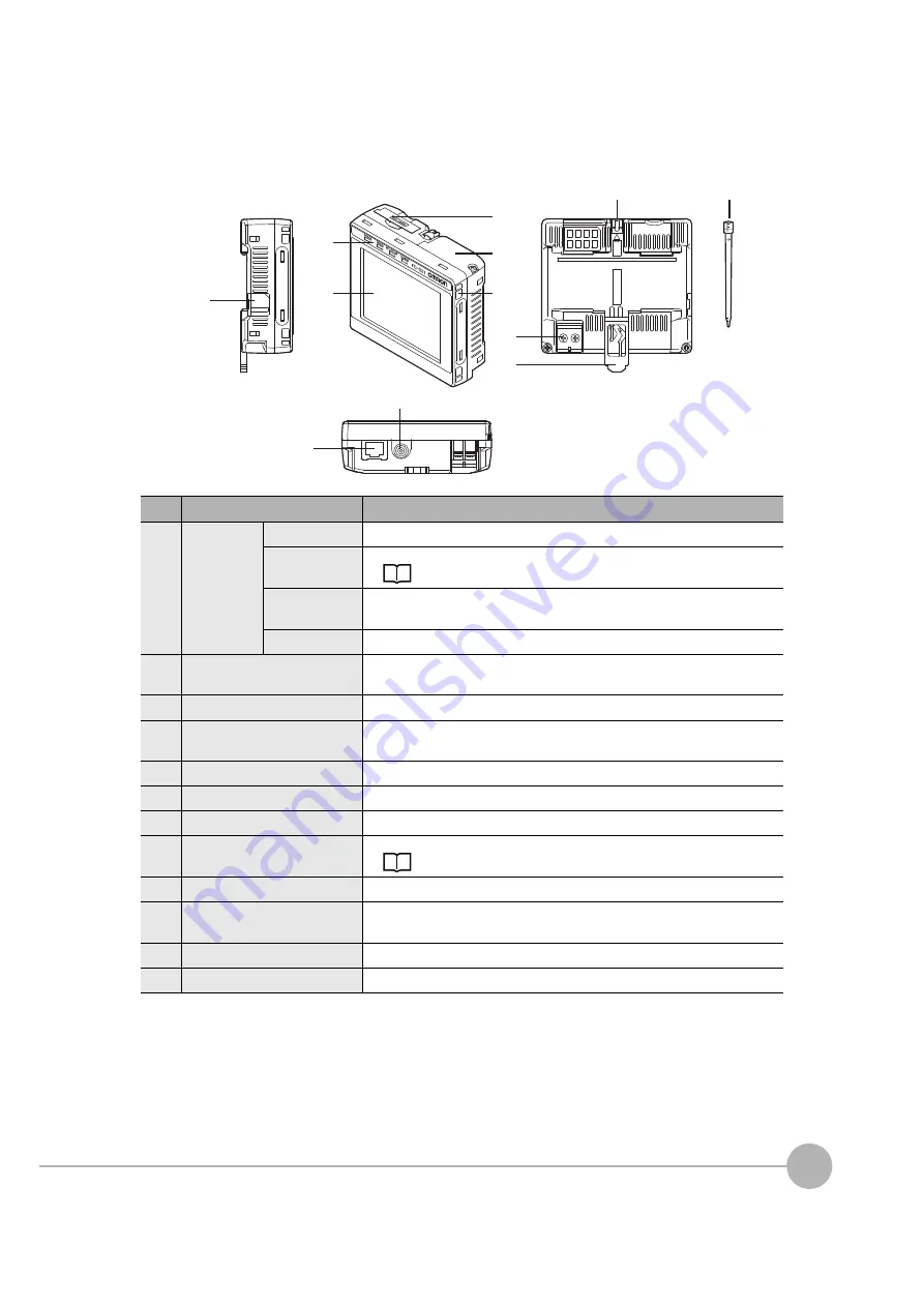
Touch Finder
*1: Applicable to the FQ2-D31 only.
No.
Name
Description
(1)
Operation
indicators
POWER
Lights green when the Touch Finder is turned ON.
ERROR
Lights red when an error occurs.
SD ACCESS
Lights yellow when an SD card is inserted.
Flashes yellow when the SD card is being accessed.
CHARGE
*1
Lights orange when the Battery is charging.
(2)
LCD/touch panel
Displays the setting menu, measurement results, and images input by the
camera.
(3)
SD card slot
An SD card can be inserted.
(4)
Battery cover
*1
The Battery is inserted behind this cover.
Remove the cover when mounting or removing the Battery.
(5)
Power supply switch
Used to turn the Touch Finder ON and OFF.
(6)
Touch pen holder
The touch pen can be stored here when it is not being used.
(7)
Touch pen
Used to operate the touch panel.
(8)
DC power supply connector
Used to connect a DC power supply.
(9)
Slider
Used to mount the Touch Finder to a DIN Track.
(10)
Ethernet port
Used when connecting the Touch Finder to the Sensor with an Ethernet
cable. Insert the connector until it locks in place.
(11)
Strap holder
This is a holder for attaching the strap.
(12)
AC power supply connector
*1
Used to connect the AC adapter.
(5)
(1)
(12)
(2)
(6)
(7)
(4)
(3)
(11)
(
8
)
(9)
(10)
Summary of Contents for FQ2 Series
Page 1: ...User s Manual Smart Camera FQ2 Cat No Z326 E1 01A ...
Page 58: ...Setting Up Ethernet 56 FQ2 User s Manual MEMO ...
Page 90: ...Adjusting the Images That Were Taken 88 FQ2 User s Manual MEMO ...
Page 190: ...Adjusting Judgement Parameters during Operation 188 FQ2 User s Manual MEMO ...
Page 234: ...Functions Related to the System 232 FQ2 User s Manual MEMO ...
Page 404: ...Basic Troubleshooting 402 FQ2 User s Manual MEMO ...
Page 513: ...Index FQ2 User s Manual 511 Index 12 ...
Page 515: ......


