


Controlling Operation and Outputting Data with the Sensor's Standard Parallel Connection
FQ2 User’s Manual
251
8
Co
ntro
llin
g Operatio
n an
d Ou
tp
utti
ng Da
ta
with a Parall
el Con
nection
Turning the ERROR Signal OFF
The ERROR signal turns ON when an error occurs.
After removing the cause of the error, turn the ERROR signal OFF using one of the following methods.
Method 1: Input an error clear command from an external device such as a PLC.
Method 2: Input a measurement trigger again.
(For example, turn the TRIG signal ON during a one-shot measurement.)
The ERROR signal will turn OFF when measurement is executed correctly.
Settings
[In/Out]
−
[I/O setting]
−
[I/O setting]
−
[Input]
−
[Input mode]
Press [Expand mode].
Wiring
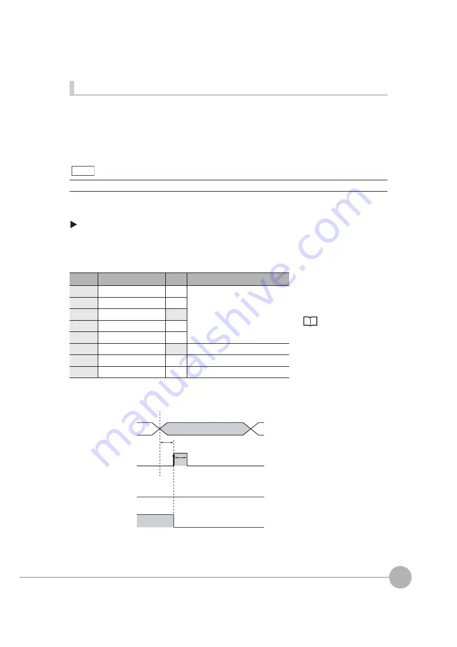
Timing Chart
This function can be used in Run Mode only.
Color
Signal
State
Description
The signals shown at the left
are used.
Refer to the following
information for signal wiring.
Gray
IN0
OFF
Command parameter for clearing errors
Green
IN1
OFF
Red
IN2
ON
White
IN3
OFF
Purple
IN4
OFF
Yellow
IN5
ON
Command input for clearing errors
Orange
OUT1 (BUSY)
--
Processing in progress (default)
Light blue
OUT2 (ERROR)
--
ERROR signal (default)
1 Turn OFF IN0 to IN1 and IN3 to IN4
and turn ON IN2.
2 Turn ON the IN5 signal while the
BUSY signal is OFF to clear the error.
Note
OFF
O
N
OFF
O
N
OFF
O
N
ERROR signal
BUSY signal
I
N
5 signal
O
N
for 1 ms min.
Allo
w
5 ms min. and then
t
u
rn O
N
I
N
5.
I
N
0 to I
N
4 signals
Summary of Contents for FQ2 Series
Page 1: ...User s Manual Smart Camera FQ2 Cat No Z326 E1 01A ...
Page 58: ...Setting Up Ethernet 56 FQ2 User s Manual MEMO ...
Page 90: ...Adjusting the Images That Were Taken 88 FQ2 User s Manual MEMO ...
Page 190: ...Adjusting Judgement Parameters during Operation 188 FQ2 User s Manual MEMO ...
Page 234: ...Functions Related to the System 232 FQ2 User s Manual MEMO ...
Page 404: ...Basic Troubleshooting 402 FQ2 User s Manual MEMO ...
Page 513: ...Index FQ2 User s Manual 511 Index 12 ...
Page 515: ......


