background image

3.2  Place of Installation

3-2

3.1.2

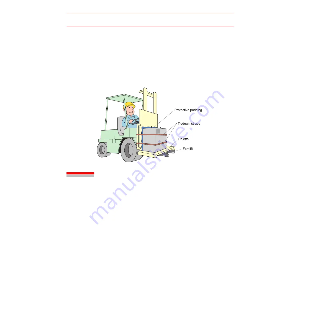
Using a Forklift to Move the Controller

Observe the following precautions when using a forklift to handle the controller:

• Confirm that there is a safe work environment and that the XRC can be transported safely 

to the installation site.

• Inform people along the forklift route that equipment is being moved in their area.
• Secure the controller so it cannot shift or fall during handling.
• Transport the controller at the lowest possible height. 
• Avoid jarring, dropping, or hitting the controller during handling. 

3.2

Place of Installation

The conditions listed below must be met before installing the XRC:

• Ambient temperature must be 0 to 45

°

 C (32 to 113

°

F) during operation and -10 to 60

°

C


(14 to 140

°

F) during transportation and maintenance.

• Humidity must be low with no condensation (under 20%RH). 
• It must be a place with little dirt, dust, or water. 
• No flammable or corrosive liquids or gases, etc. in the area. 
• Little jarring or potential for striking of the XRC (under 0.5 oscillation).
• No large electric noise source (such as a TIG welding device, etc.) nearby. 
• No potential for collision with moving equipment such as forklifts.

Summary of Contents for SK300X

Page 1: ...Motoman Inc and may not be copied reproduced or transmitted to other parties without the expressed written authorization of Motoman Inc 2001 by MOTOMAN All Rights Reserved Because we are constantly im...

Page 2: ......

Page 3: ...N i SK300X Manipulator Manual XRC 2001 Section Page 1 INTRODUCTION 1 1 2 SAFETY 2 1 3 XRC SETUP 3 1 4 SK300X INSTRUCTIONS 4 1 5 XRC INSTRUCTIONS NAS 2001 5 1 6 XRC INSTRUCTIONS GENERAL R2 6 1 7 SK300X...

Page 4: ...SK300X Manipulator Manual XRC 2001 ii MOTOMAN NOTES...

Page 5: ...e following sections SECTION 1 INTRODUCTION Provides general information about the structure of this manual a list of reference documents and customer service information SECTION 2 SAFETY Provides inf...

Page 6: ...Manual for Spot Welding P N 142101 1 Operator s Manual for Arc Welding P N 142098 1 Vendor manuals for system components not manufactured by Motoman 1 3 Customer Service Information If you are in nee...

Page 7: ...INTRODUCTION MOTOMAN 1 3 SK300X Manipulator Manual XRC 2001 NOTES...

Page 8: ...ogram and maintain the robot cell The robot must not be operated by personnel who have not been trained We recommend that all personnel who intend to operate program repair or use the robot system be...

Page 9: ...diate and imminent hazards that if not avoided will result in immediate serious personal injury or loss of life in addition to equipment damage WARNING Information appearing under the WARNING caption...

Page 10: ...puts and Outputs The robot must be placed in Emergency Stop E STOP mode whenever it is not in use In accordance with ANSI RIA R15 06 section 6 13 4 and 6 13 5 use lockout tagout procedures during equi...

Page 11: ...d with the operation of the equipment must understand potential dangers of operation Programming tips are as follows Any modifications to PART 1 of the MRC controller PLC can cause severe personal inj...

Page 12: ...equipment for proper operation Repair or replace any non functioning safety equipment immediately Inspect the robot and work envelope to ensure no potentially hazardous conditions exist Be sure the ar...

Page 13: ...changes are made A backup must always be made before any servicing or changes are made to options accessories or equipment to avoid loss of information programs or jobs Do not enter the robot cell wh...

Page 14: ...thoroughly and retain for future reference MOTOMAN INSTRUCTIONS MOTOMAN SETUP MANUAL MOTOMAN ooo MANIPULATOR INSTRUCTION MANUAL YASNAC XRC INSTRUCTION MANUAL YASNAC XRC OPERATOR S MANUAL YASNAC XRC OP...

Page 15: ...ng this product The drawings and photos in this manual are representative examples and differences may exist between them and the delivered product YASKAWA may modify this model without notice when ne...

Page 16: ...rtant items Indicates a potentially hazardous situation which if not avoided could result in death or serious injury to personnel Indicates a potentially hazardous situation which if not avoided could...

Page 17: ...obot work envelope to teach a job Operator injury can occur if the Teach Lock is not set and the manipulator is started from the playback panel Observe the following precautions when performing teachi...

Page 18: ...essary processing has been performed Check for problems in manipulator movement Check for damage to insulation and sheathing of external wires Always return the programming pendant to the hook on the...

Page 19: ...e g ENTER Symbol Keys The keys which have a symbol printed on them are not denoted with but depicted with a small picture e g page key The cursor key is an exception and a picture is not shown Axis Ke...

Page 20: ...ached to the manipulator Observe the precautions on the warning labels Failure to observe this caution may result in injury or damage to equipment Refer to the manipulator manual for the warning label...

Page 21: ...viii...

Page 22: ...2 2 3 Installation 3 1 Handling Procedure 3 1 3 1 1 Using a Crane to Move the Controller 3 1 3 1 2 Using a Forklift to Move the Controller 3 2 3 2 Place of Installation 3 2 3 3 Location 3 3 3 4 Mounti...

Page 23: ...on the Servo Power 5 2 5 2 1 During Play Mode 5 2 5 2 2 During Teach Mode 5 3 5 3 Turning the Power Off 5 4 5 3 1 Turning the Servo Power Off Emergency Stop 5 4 5 3 2 Turning the Main Power Off 5 4 6...

Page 24: ...for safe and proper operation of the MOTOMAN Chapter 2 explains how to receive the manipulator and its support equipment Chapter 3 explains XRC installation location and setup Chapter 4 explains how...

Page 25: ...xii...

Page 26: ...d arm movements etc which can pose safety hazards Read and understand the instruction manuals and related documents and observe all pre cautions in order to avoid the risk of injury to personnel and d...

Page 27: ...EC Prepare SAFETY WORK REGULATIONS based on concrete policies for safety management complying with related laws Observe the MANIPULATING INDUSTRIAL ROBOTS SAFETY ISO 10218 for safe operation of the ro...

Page 28: ...the back cover of this manual It is important to have and be familiar with all manuals concerning the MOTOMAN You should have the four manuals listed below MOTOMAN SETUP MANUAL MOTOMAN ooo INSTRUCTION...

Page 29: ...in the factory Failure to observe these cautions may result in fire electric shock or injury due to contact with the manipulator and other equipment Strictly observe the following items Always wear ap...

Page 30: ...RC or other controllers and avoid inadvertently pushing buttons Failure to observe this caution may result in injury or damage by unexpected movement of the manipulator Never allow unauthorized person...

Page 31: ...ow to install the manipulator Confirm that the area is large enough so that the fully extended manipu lator arm with tool will not reach a side wall safeguards or the control ler Failure to observe th...

Page 32: ...ng the XRC please check the following As a rule handling of XRC must be performed using a crane with wire rope threaded through attached eyebolts Be sure to use wire that is strong enough to handle th...

Page 33: ...e Install the XRC outside the safeguard of the manipulator s safety enclo sure Failure to observe this precaution may result in injury or damage to equipment resulting from contact with the manipulato...

Page 34: ...n accordance with the connection diagram There is a danger of equipment damage or injury due to miswiring and unexpected move ment of the equipment Take precautions when wiring and piping between the...

Page 35: ...e of the enclosure The gate of the enclosure must be equipped with a safety interlock Be sure the interlock operates correctly before use Failure to observe this caution may result in a serious accide...

Page 36: ...found in the specifications section of the manipulator manual Failure to observe this caution may result in injury or damage to equipment Teach jobs from outside the manipulator s work area whenever...

Page 37: ...sonnel operating the manipulator from the playback panel Prior to operation be sure there are no personnel in the manipulator s working envelope The following operations should always be per formed fr...

Page 38: ...to insulation and sheathing of cables Always return the programming pendant to the hook on the front of the controller after use The programming pendant can be damaged if it is left on the floor or i...

Page 39: ...manipulator and YASNAC XRC are illegible clean the labels so that they can be read clearly Note that some local laws may prohibit equipment operation if safety labels are not in place Contact your YAS...

Page 40: ...sal When disposing of the MOTOMAN follow the applicable national local laws and regulations Anchor the manipulator well even when temporarily storing it before disposal Failure to observe this precaut...

Page 41: ...1 7 Notes on MOTOMAN Disposal 1 16...

Page 42: ...Confirm the contents of the delivery when the product arrives Standard delivery includes the following five items Information for the content of optional goods is given separately Manipulator XRC Prog...

Page 43: ...2 2 Order Number Confirmation 2 2 2 2 Order Number Confirmation Confirm that the order number pasted on the manipulator and XRC match The order number plates are affixed to the figure below Example...

Page 44: ...r handling and make sure they are securely fastened before hoisting Crane sling and forklift operations must be performed only by autho rized personnel Failure to observe this caution may result in in...

Page 45: ...ight Avoid jarring dropping or hitting the controller during handling 3 2 Place of Installation The conditions listed below must be met before installing the XRC Ambient temperature must be 0 to 45 C...

Page 46: ...an easily inspect it when the door is open Install the controller at least 500mm from the nearest wall to allow maintenance access Shows the external dimensions 1000 mm or more 1000 mm or more 1000 mm...

Page 47: ...ontroller Attach the controller to the floor using user supplied brackets made according to the specifica tions shown below Refer to the Instruction Manual for information on installation of the manip...

Page 48: ...acitors inside the controller store electricity after power is turned off Exercise caution whenever handling circuit boards Failure to observe this caution may cause electrical shock Power cannot be t...

Page 49: ...equipment dam age One connects the manipulator and XRC Another connects the XRC and peripheral equipment A wrong connection can cause damage to electronic equipment Clear the area of all unauthorized...

Page 50: ...pply consists of AC200 220V 10 15 and 50 60Hz 2Hz 2Hz The power failure processing circuit operates when there is a temporary power frequency black out or drop in voltage and the servo power turns off...

Page 51: ...e breaker which can handle high frequencies Leakage breakers which cannot handle high fre quencies may malfunction Even with a leakage breaker installed there is still a possibility of some high frequ...

Page 52: ...capacity is different depending on work conditions Inquire at the nearest branch office listed on the back cover for information when selecting the transformer Cable Sizes and Switch Capacities Manip...

Page 53: ...and programming pendant is shown below 4 3 1 Connecting the Primary Power Supply 1 Open the front door of the XRC 1 Insert the door handle in the door lock on the front of XRC two places and rotate it...

Page 54: ...cable through it It is located on the top or on the left side of the XRC Attach the plate and cable firmly so that it won t shift or slide out of place 1 Pull off the top cover of the switch which is...

Page 55: ...nding in accordance with all relevant local and national electrical codes Grounding wire must be 8 0 mm2 or larger Exclusive Grounding The customer must prepare the ground wire Don t connect the groun...

Page 56: ...4 3 Connection Methods 4 9 4 Install the cover Install the Switch Cover 4 3 2 Connecting the Power Supply 1 Remove the cover from the left side of the controller cabinet Detaching the Cable Hole Cover...

Page 57: ...and the position of the pins of the manipulator Push the cable connector into the manipulator side connector firmly and tighten securely 4 Close the XRC door 1 Close the door gently 2 Rotate the door...

Page 58: ...cting the Programming Pendant Connect the programming pendant cable to the connector on the left side of the controller cabinet Connecting the Programming Pendant The manipulator XRC and the programmi...

Page 59: ...4 3 Connection Methods 4 12...

Page 60: ...hen the XRC main power is turned on and the star tup display is shown on the programming pendant screen Confirm that nobody is present in the working envelope of the manipula tor when turning on XRC p...

Page 61: ...in the play mode edit job if the XRC is in the teach mode and the cursor position in the job 5 2 Turning on the Servo Power 5 2 1 During Play Mode The worker s safety is secure if the safety plug is t...

Page 62: ...back panel lights when the operator grips the deadman switch Servo Power ON OFF Deadman Switch When the operator squeezes the deadman switch the servo power turns ON However if the operator squeezes t...

Page 63: ...off the servo power turn off the main power Turning the Servo Power Off Pressing the emergency stop button on either the programming pen dant or the playback box will turn off servo power The brake o...

Page 64: ...predetermined operating procedure Always have an escape plan in mind in case the manipulator comes toward you unexpectedly Improper or unintentional manipulator movement can result in injury Ensure no...

Page 65: ...them before resuming operation Specifically check for Problems in manipulator motion Damage to cables Always return the programming pendant to its specified position after use The programming pendant...

Page 66: ...lator by pressing the axis keys on the programming pendant This figure illustrates each axis of motion in the joint coordinate system Be sure to remove all items from the area before moving the manipu...

Page 67: ...6 1 Movement of the Axes 6 4...

Page 68: ...e manipulator comes toward you unexpectedly Ensure that you have a safe place to retreat in the event of an emer gency Improper or unintentional manipulator operation can result in injury Prior to per...

Page 69: ...k for problems in manipulator movement Check for damage to insulation and sheathing of external wires Return the programming pendant to its specified position after use If the programming pendant is l...

Page 70: ...ition display is shown 1 Move each manipulator axis using the programming pendant axis key Adjust each axis to the position of 0 pulse Make sure the manipulator servo power supply is off and that the...

Page 71: ...if home position mark for each axis is matched accurately Contact Customer Service if you encounter any problems performing home position cali bration S AXIS L AXIS opposite side The angle of the U ax...

Page 72: ...he operations are explained carefully in order Operator s Manual Composed of several sections each corresponding to operation of the system Work involving setting and diagnosis of the controller alarm...

Page 73: ...8 2...

Page 74: ......

Page 75: ...JING OFFICE Room No 301 Office Building of Beijing Intemational Club 21 Jianguomenwai Avenue Beijing 100020 China SHANGHAI OFFICE 27 Hui He Road Shanghai 200437 China YASKAWA JASON HK COMPANY LIMITED...

Page 76: ...ior to initial operation read these instructions thoroughly and retain for future reference MOTOMAN INSTRUCTIONS MOTOMAN SETUP MANUAL MOTOMAN SK300X SK300X 170 SK300X 400 INSTRUCTIONS YASNAC XRC INSTR...

Page 77: ...s and photos in this manual are representative examples and differences may exist between them and the delivered product YASKAWA may modify this model without notice when necessary due to product impr...

Page 78: ...a potentially hazardous situation which if not avoided could result in death or serious injury to personnel Indicates a potentially hazardous situation which if not avoided could result in minor or m...

Page 79: ...k envelope to teach a job Operator injury can occur if the Teach Lock is not set and the manipulator is started from the playback panel Observe the following precautions when performing teaching opera...

Page 80: ...e that all other necessary processing has been performed Check for problems in manipulator movement Check for damage to insulation and sheathing of external wires Always return the programming pendant...

Page 81: ...e labels Also an indentification label with important information is placed on the body of the manipula tor Prior to operating the manipulator confirm the contents MOTOMAN TYPE ORDER NO PAYLOAD kg MAS...

Page 82: ...the Manipulator is Mounted Directly on the Floor 3 4 3 3 Location 3 5 4 Wiring 4 1 Grounding 4 1 4 2 Cable Connection 4 2 4 2 1 Connection to the Manipulator 4 2 4 2 2 Connection to the XRC 4 2 5 Basi...

Page 83: ...for R Axis Speed Reducer 9 10 n Grease Replenishment Refer to Fig 24 R Axis Speed Reducer Diagram 9 10 n Grease Replacement Refer to Fig 24 R Axis Speed Reducer Diagram 9 11 9 2 5 Grease Replenishment...

Page 84: ...ions ordered should be checked as well Manipulator XRC Programming Pendant Feeder Cable Between Controller and Manipulator Confirm that the manipulator and the XRC have the same order number Special c...

Page 85: ...ponds to the XRC The order number is located on a label as shown below a XRC Front View b Manipulator Side View Fig 1 Location of Order Number Labels Label Enlarged view THE MANIPULATOR AND THE CONTRO...

Page 86: ...nipulator is fixed with jigs before transporting and lift it in the posture as shown in Fig 2 Transporting Position Fig 2 Transporting Position Sling applications and crane or forklift operations must...

Page 87: ...other than transporting the manipulator Mount the shipping bolts and jigs for transporting the manipulator Avoid exerting force on the arm or motor unit when transporting use caution when using transp...

Page 88: ...in injury or damage Do not start the manipulator or even turn on the power before it is firmly anchored The manipulator may overturn and cause injury or damage Do not install or operate a manipulator...

Page 89: ...arriers interlock barriers perimeter guarding awareness barriers and awareness signals 3 2 Mounting Procedures for Manipulator Baseplate The manipulator should be firmly mounted on a baseplate or foun...

Page 90: ...fixture The thickness of the common base is 50mm or more and a size of the anchor bolt of M20 or larger is recommended Affix the manipulator by fastening the plate with the eight M20 mm anchor bolts...

Page 91: ...epulsion forces of the manipulator as shown in Table 1 As a rough standard when there is a concrete thickness floor of 200mm or more the base of the manipulator can be fixed directly to the floor with...

Page 92: ...ioned environmental conditions 0 to 45 C Ambient temperature 20 to 80 RH no moisture Free from dust soot or water Free from corrosive gases or liquid or explosive gases Free from excessive vibration l...

Page 93: ...3 3 Location 3 6...

Page 94: ...ON Failure to observe this warning may result in fire or electric shock Wiring must be performed by authorized or certified personnel Failure to observe this caution may result in fire or electric sho...

Page 95: ...main key positions of the manipulator and insert cables in the order of 2BC 3BC and 1BC and then set the lever until hearing a click 4 2 2 Connection to the XRC Remove the cover on the XRC side Pass...

Page 96: ...4 2 Cable Connection 4 3 Fig 6 a Power Cables 1BC 2BC XIU01 CN25 WRCA01 CNPG456 WRCA01 CNPG123 Connection to the XRC Connection to the manipulator 1BC 2BC Signal cable Power cable...

Page 97: ...4 2 Cable Connection 4 4 Fig 6 b Power Cables 3BC Fig 7 a Power Connection to the Manipulator Connection to the XRC Connection to the manipulator CACR SK300AAB 3BC Power cable...

Page 98: ...5 Signal Cable Tighten the screws with screw driver Power Cable Grounding plate for signal and power line Terminal No E Signal Cable Connector No WRCA01 CNPG456 upper WRCA01 CNPG123 lower Power Cable...

Page 99: ...4 2 Cable Connection 4 6...

Page 100: ...0 s 1 31 rad s 75 s 1 40 rad s 80 s L Axis 1 22 rad s 70 s 1 31 rad s 75 s 1 40 rad s 80 s U Axis 1 22 rad s 70 s 1 31 rad s 75 s 1 40 rad s 80 s R Axis 1 40 rad s 80 s 1 75 rad s 100 s 2 09 rad s 120...

Page 101: ...Part Names and Working Axes 5 2 5 2 Part Names and Working Axes Fig 8 Part Names and Working Axes 5 3 Baseplate Dimensions Fig 9 Baseplate Dimensions mm 90 860 760 640 860 760 640 394 8 f28 Hole A Vie...

Page 102: ...5 4 Dimensions and Working Range 5 3 5 4 Dimensions and Working Range Fig 10 a Dimesions and Working Range YR SK300 J0...

Page 103: ...5 4 Dimensions and Working Range 5 4 Fig 10 b Dimesions and Working Range YR SK300 J1...

Page 104: ...5 4 Dimensions and Working Range 5 5 Fig 10 c Dimesions and Working Range YR SK300 J2...

Page 105: ...Working Range Fig 11 B Axis Working Range 5 6 Alterable Working Range The working range of the S Axis can be altered according to the operating conditions as shown in Table 3 S Axis Working Range If a...

Page 106: ...tational unit When the volume load is small refer to the moment arm rating shown in Fig 12 Moment Arm Rating The allowable total inertia is calculated when the moment is at the maximum Contact your Ya...

Page 107: ...2 Fig 12 Moment Arm Rating T B Axes Rotation Center Line T B Axes Rotation Center Line T B Axes Rotation Center Line Point P Point P Point P B Axis Rotation Center Line B Axis Rotation Center Line B...

Page 108: ...er to see the tram marks it is recommended that the attachment be mounted inside the fitting Fitting depth of inside and outside fittings must be 8mm or less Fig 13 Wrist Flange Wash off anti corrosiv...

Page 109: ...6 2 Wrist Flange 6 4...

Page 110: ...tions should be observed Fig 14 Clamp and Tapped Holes Table 5 Constraint for Attaching Application Note A Cable Processing Attaching load weight is 300kg max for YR SK300 J0 170kg max for YR SK300 J1...

Page 111: ...The maximum pressure for the air duct is 490kPa 5kgf cm2 and its inside diameter is 8mm Fig 15 Incorporated Wire and Airduct The same pin number 1 17 of two connectors is connected in the lead line of...

Page 112: ...of S Axis Limit Switch 8 1 8 Motoman Construction 8 1 Position of S Axis Limit Switch The limit switches for the S Axis are located as shown in Fig 16 Location of Limit Switches Fig 16 Location of Li...

Page 113: ...ber and location of connectors see Fig 17 Location and Numbers of Connec tors and Table 6 List of Connector Types Fig 17 Location and Numbers of Connectors Table 6 List of Connector Types Name Type of...

Page 114: ...P P P P P BATTERY K P 1CN C DATA 1 BAT T P P S J G H OBT FG2 5V 0V No 3CN J D 3CN C D T S G H FG1 DATA 2 DATA 2 5V OBT BAT DATA 1 0V No 2CN U AXIS PG L AXIS PG S AXIS PG DATA 3 DATA 3 OBT BAT 0V FG3...

Page 115: ...YB SM No 15CN 15CN A F BB3 E D C B BA3 MW3 ME3 MV3 MU3 YB SM U AXIS A1 B2 A2 B1 ME4 BA4 ME4 MW4 MW4 MV4 MU4 MV4 MU4 CN1 2 CN2 4 CN2 5 CN2 2 CN2 1 CN2 7 CN2 8 CN1 5 CN1 4 CN1 1 A2 A1 B2 B1 MU5 MV5 MU5...

Page 116: ...ersonnel are to do inspection work Before maintenance or inspection be sure to turn the main power sup ply off and put up a warning sign ex DO NOT TURN THE POWER ON Failure to observe this warning may...

Page 117: ...lead Visual Check for damage and deterioration of leads Working area and manipulator Visual Clean the work area if dust or spatter is present Check for damage and outside cracks LU axes motor Visual C...

Page 118: ...lfunc tion Replace if nec essary Supply grease 3 6000H cycle See Par 9 2 2 Replace grease 3 12000H cycle See Par 9 2 2 L U axis speed reducer Grease Gun Check for malfunc tion Replace if nec essary Su...

Page 119: ...4 Inspection No correspond to the numbers in Fig 19 Inspection Parts and Inspection Numbers 5 The occurrence of a grease leakage indicates the possibility that grease has seeped into the motor 6 This...

Page 120: ...in Table 7 Inspection Items Table 8 Inspection Parts and Grease Used No Grease Used Inspected Parts 16 17 18 19 Molywhite RE No 00 Speed Reducers for all Axes B and T axis Gears 10 14 20 Alvania EP G...

Page 121: ...9 6 9 2 Notes on Maintenance Procedures 9 2 1 Battery Unit Replacement If a battery alarm occurs in the XRC replace the battery according to the following procedure Fig 20 a Battery Location Back View...

Page 122: ...Mount the battery unit with the screw connect the grease tube to the union and then mount the connector base Remove the old battery unit after connecting the new one so that the encoder absolute data...

Page 123: ...ement Refer to Fig 22 S Axis Speed Reducer Diagram 1 Remove the So exhaust plug 2 Inject the grease into the Si grease inlet using a grease gun 3 The grease replacement is complete when new grease app...

Page 124: ...Uo exhaust plugs 2 Inject grease into the Li and Ui grease inlet using a grease gun 3 Move the L and U Axis for a few minutes to discharge the excess grease 4 Wipe the Lo and Uo exhaust plugs with a c...

Page 125: ...for R Axis Speed Reducer Fig 24 R Axis Speed Reducer Diagram n Grease Replenishment Refer to Fig 24 R Axis Speed Reducer Diagram 1 Remove the cap and the Ro exhaust plug 2 Inject grease into the Ri g...

Page 126: ...ew grease appears in the Ro exhaust ports The new grease can be distinguished from the old grease by color 4 Move the R Axis for a few minutes to discharge the excess grease 5 Wipe the Ro exhaust plug...

Page 127: ...grease into the Bi and Ti grease inlets G Nipple A M6F 4 The grease replacement is complete when new grease appears in the Bo exhaust ports The new grease can be distinguished from the old grease by...

Page 128: ...plenishment for L Axis Cross Roller Bear ing Fig 27 L Axis Cross Roller Bearing 1 Remove the plug for air flow 2 Inject grease Lc grease inlet using a grease gun 3 Reinstall the plug for air flow Grea...

Page 129: ...Roller Bearing 2 Inject grease Lc grease inlet using a grease gun 3 Reinstall the plug for air flow 9 2 9 Grease Replenshment for R Axis Taper Roller Bear ings YR SK300 J2 Fig 29 R Axis Taper Roller B...

Page 130: ...ow 6ps refer to Fig 30 Link Connection Part Grease type Alvania EP grease 2 Amount of grease 12cc Grease type Alvania EP grease 2 Amount of grease 6cc 12cc for 1st supply Do not inject excessive greas...

Page 131: ...art Fig 31 Balancer Connection Part 1 Remove the plug for air flow 4ps refer to Fig 31 Balancer Connection Part Grease type Alvania EP grease 2 Amount of grease 5cc 10cc for 1st supply Do not inject e...

Page 132: ...attery backup connector of the motor 2 Connect the battery unit connection cable HW9470945 A for the motor with the bat tery backup connector of the motor 3 Connect the SLU axes battery unit HW9470932...

Page 133: ...9 2 Notes on Maintenance Procedures 9 18...

Page 134: ...0 SK300X 400 Rank Parts No Name Type Manufacturer Qty Qty per Unit Remarks A 1 Grease Molywhite RE No 00 Yaskawa Electric Corporation 16kg for all axes speed reducers and wrist units A 2 Grease Alvani...

Page 135: ...400 Yaskawa Electric Corporation 1 1 B 14 Wrist Unit HW9171115 A Sk300X Yaskawa Electric Corporation 1 1 HW9171115 B Sk300X 170 HW9171115 C Sk300X 400 C 15 AC Servomotor for S L U Axis HW9381608 A Ya...

Page 136: ...11 1 S Axis Driving Unit 11 1 11 Parts List 11 1 S Axis Driving Unit...

Page 137: ...S head 1 0030 NO 3 5 312 O ring 1 0031 HW9403722 1 Cover 2 0032 M6x12 Screw 16 0032AA 2H 6 Spring washer 16 0049 HW9404016 1 Guide rail 1 0049AA HW9406016 2 Guide rail 1 0049AB M5x14 Flat countersuck...

Page 138: ...11 2 L U Axis Driving Unit 1 11 3 11 2 L U Axis Driving Unit 1...

Page 139: ...VAL 2 Accessary 1 0085 M3X14 Screw 2 0086 M3 Spring washer 2 0087 HW8415663 1 LS base 1 0094 HW9403766 1 Cver 1 0095 PT1 4 Plug 1 0096 SLE 062V Union 1 0097 M6x12 Screw 4 0098 M6 Washer 4 0099AA TP6...

Page 140: ...11 3 L U Axis Driving Unit 2 11 5 11 3 L U Axis Driving Unit 2...

Page 141: ...320 HW9481247 A Pulley 1 0321 HW9481248 A Pulley 1 0322 M10x30 Socket screw 2 0323 2H l10 Spring washer 2 0324 SGMGH 30A2A AC servo motor 3 0325 M12x35 Socket screw 12 0326 2H 12 Spring washer 12 0327...

Page 142: ...i Taiwan BEIJING OFFICE Room No 301 Office Building of Beijing Intemational Club 21 Jianguomenwai Avenue Beijing 100020 China SHANGHAI OFFICE 27 Hui He Road Shanghai 200437 China YASKAWA JASON HK COMP...

Page 143: ...nstructions thoroughly and retain for future reference MOTOMAN INSTRUCTIONS MOTOMAN SETUP MANUAL MOTOMAN INSTRUCTIONS YASNAC XRC INSTRUCTIONS YASNAC XRC OPERATOR S MANUAL YASNAC XRC OPERATOR S MANUAL...

Page 144: ...B HFSBG FG BAK GB FSBK IFG HA G EOL TB GB AA HFSBG K BAK GB GBDA HBK PBIFGB FDBG E N E DGFK HEL 9 B KG J N K D FEF E A GB GBDGB B E E SB BC DAB K K IIBGB HB O BC E PBEJBB E B K E B KBA SBGBK DGFK HEL...

Page 145: ...ly hazardous situation which if not avoided could result in death or serious injury to personnel Indicates a potentially hazardous situation which if not avoided could result in minor or moderate inju...

Page 146: ...JFGX B SBAFDB EF EB H FPL Operator injury can occur if the Teach Lock is not set and the manipulator is started from the playback panel 9 P BGSB E B IFAAFJ N DGBH E F J B DBGIFG N EB H N FDBG E F J E...

Page 147: ...AOM K PB GB E E AA FE BG BHB GO DGFHB N PBB DBGIFG BKL W1 BHX IFG DGFPAB D A EFG FSB B EL W1 BHX IFG K NB EF A E F K B E N FI BCEBG A J GB L 9 AJ O GBE G E B DGFNG N DB K E EF E B FFX F E B 3 1 H P BE...

Page 148: ...ex ENTER Symbol Keys The keys which have a symbol printed on them are not denoted with but depicted with a small picture ex page ke The cursor key is an exception and a picture is not shown Axis Keys...

Page 149: ...4L L6 Specific I O Circuit Board 1 JARCR XCI01 and Specific I Circuit Board 2 JARCR XCU01B 2 11 Direct IN 2 12 Connected Jumper Leads Before Shipment 2 13 Deadman Switch Signal Output 2 14 Connection...

Page 150: ...d 2 72 Arc Welding Application 2 72 Inspections L6 Regular Inspections 3 1 L4 XRC Inspections 3 2 L4L6 Checking if the Doors are Firmly Closed 3 2 L4L4 Checking for Gaps or Damage in the Sealed Constr...

Page 151: ...AAFJ N DGBH E F J B DBGIFG N EB H N FDBG E F J E E B JFGX N B SBAFDB FI E B D A EFGR W AJ O S BJ E B D A EFG IGF E B IGF EL W AJ O IFAAFJ E B DGBKBEBG BK FDBG E N DGFHBK GBL W AJ O SB B H DB DA K H B...

Page 152: ...BHX IFG DGFPAB D A EFG FSB B EL W 1 BHX IFG K NB EF E B A E F K B E N FI BCEBG A J GB L 9 AJ O GBE G E B DGFNG N DB K E EF E DBH I BK DF E F IEBG BL If the programming pendant is inadvertently left o...

Page 153: ...oltage on customer side 480 VAC is set before ship ment If the transformer is not used the specification is three phase AC200 220V 10 15 at 50 60Hz 2 Hz Grounding Grounding resistance 100 or less Excl...

Page 154: ...ng Speed Limit User definable Deadman Switch 3 position type Servo power can be turned on at the mid position only Located on programming pendant Collisionproof Frames S axis frame doughnut sector Cub...

Page 155: ...bot stop Execution of some instruc tions during robot motion Operation Instruc tions Preparing the operation instructions for each application Arc ON Arc OFF etc Variable Global variable Local variabl...

Page 156: ...AF_F1 SAF_F2 SAF_F2 14 15 16 16 15 14 EXHOLD1 EXHOLD1 EXHOLD2 EXHOLD2 9 10 11 12 12 11 10 9 EXSVON2 8 8 PPESPOUT EXSVON1 6 6 CN28 10 8 7 6 5 4 3 2 1 9 EXBRK EXBRK EXNCM EXNCM EXTUDIN ON_EN1 ON_EN1 G3...

Page 157: ...CN01 IO 0 6XT OFF QS1 QS3 10A 250V 1FU 2FU 10A 250V 1XT USCC3I QS2 QS3 Fuse holders Fuse Refer to the Following table Brake release control board CN3 CN4 CN1 CN5 CN2 I O unit CN31 CN30 CN32 CN26 CN25...

Page 158: ...nd QS3 CN5 CN3 CN4 CN1 CN2 CN32 CN30 CN31 CN26 CN24 CN23 CN25 CN29 EV3 CN20 EV2 EV1 CN21 CN22 CN05 1 2 3 4 5 5 4 3 2 1 EXSVON1 EXESP 2 EXESP2 EXESP1 EXESP1 CN06 PPESPOUT PPESPIN PPESPIN PPESPOUT PPESP...

Page 159: ...r to the following table USCC3I CN4 CN3 CN1 CN2 CN5 Brake release control board JZRCR XCO02B CPU unit EV3 CN31 CN30 CN32 CN25 CN26 CN22 CN21 CN20 CN23 CN24 CN29 EV2 JZNC XRK01B 1 Power ON unit DATE SE...

Page 160: ...RVOPACK QS1 Type UP200 UP130 UP165 UP165 100 YASNAC XRC Time delay fuses of class CC are used for QS1 and QS3 CN31 CN30 CN32 CN25 CN26 CN22 CN21 CN20 CN23 CN24 CN29 CN06 CN05 CN13 CN12 CN10 CN11 CN44...

Page 161: ...P100 RB03 Brake operation panel JZRCR XFL02B 40A 40A 40A 40A Sectional view A A CACR UP130AABY18 CACR UP130AABY21 CACR SK300AAB CACR SK300AAB 40A 40A 40A 40A A JZRCR XPU10B A Refer to the following ta...

Page 162: ...tem SV3X Small Capacity type Right side view Cooling System Except for SV3X Small Capacity type Right side view 1KM Servo Top Fan Backside Duct Fan Air Inlet Servopack Air Outlet S Servopack Natural h...

Page 163: ...GIFG N EB H N FDBG E F J E E B JFGX N B SBAFDB FI E B D A EFGR W AJ O S BJ E B D A EFG IGF E B IGF EL W AJ O IFAAFJ E B DGBKBEBG BK FDBG E N DGFHBK GBL W AJ O SB B H DB DA K H B E B D A EFG HF B EFJ G...

Page 164: ...FHBK GB DG FG EF DBGIFG N EB H W N FDBG E F L 0I DGFPAB GB IF KM HFGGBHE E B BK EBAOM K PB GB E E AA FE BG BHB GO DGFHB N PBB DBGIFG BKL W 1 BHX IFG DGFPAB D A EFG FSB B EL W 1 BHX IFG K NB EF A E F K...

Page 165: ...ATE NJ2096 1 JAPAN TYPE SER NO YASKAWA ELECTRIC CORPORATION Noise filter 1Z 5X Single 200 VAC Output connector Conector output etc Resister RB 4X Contactor output 10A 250V 2FU 10A 250V 1FU 1X Single p...

Page 166: ...the button BRAKE RELEASE held pressed press the button of axis for which the brake is to be released The brake for the corresponding axis is released as long as the button is pressed 9 V EH F OF G IBB...

Page 167: ...a serial communication board JANCD XIF03 This board has the PC card interface and Serial interface for RS 232C The JANCD XMM 01 board option can be installed when CMOS memory is expanded JANCD XCP01...

Page 168: ...tuation Range 10 to 15 170 to 242VAC Frequency 50 60Hz 2Hz 48 to 62Hz Output Voltage 5VDC 10A 24VDC 4 0A Indicator Overheat Detector It is detected when the temperature inside of the controller is abo...

Page 169: ...power turn the main switch to the ON posi tion then turning on the control powersupply If the controller is not located at the workplace the control power supply can be turned ON and OFF by input from...

Page 170: ...tool downward Direction of the arrow 3 Remove the wiring tool from the connector Complete The wiring tool for WAGO connector should be kept for future use Wire Bare length 8 to 9 mm A part Attachment...

Page 171: ...e screw on A part of the connector by using small size flat tipped screw driver 2 Insert a wire into the B part of connector and tigten the A part screw by using a small size flat tipped screwdriver R...

Page 172: ...Playback Panel CN10 11 12 and 13 General I O Signal Connector CN41 For connection to Power ON unit CN40 Forced Reset Full speed Set Switch to Safe Speed Hanger Switch PHENIX connector Refer to Wiring...

Page 173: ...points 8 points Direct input 3 points Deadman Switch Control Circuit JZRCR XCO02B Specific Input Circuit Board Allocation and Connection Diagram 9 TBIFGB BM GB FSB O DBG AB K IGF E B DBH I H D E N A L...

Page 174: ...nally connected JZRCR XCO02B Specific I O Circuit Board Allocation and Connection Diagram 1 2 3 4 5 6 7 8 EXDIN1 EXDIN1 EXDIN2 EXDIN2 EXDIN3 EXDIN3 EXDIN4 EXDIN4 CN44 24V DIN1 DIN2 DIN3 DIN4 YASNAC XR...

Page 175: ...9 on the specific input circuit board JARCR XCI01 are set across 2 and 3 of SW 1 1 and 2 of SW8 and 1 and 2 of SW9 JZRCR XCO02B Specific I O Circuit Board Allocation and Connection Diagram CN06 1 2 3...

Page 176: ...d Allocation and Connection Diagram CN06 1 2 3 4 5 6 7 8 9 10 11 12 13 14 15 16 YASNAC XRC JZRCR XCO02B JARCR XCI01 PPESPOUT PPESPOUT PPESPIN PPESPIN PBESPOUT PPESPOUT PBESPIN PBESPIN DSWOUT DSWOUT RD...

Page 177: ...JZRCR XCO02B 2 Connect CN06 16 and 15 of the I O unit JZRCR XCO02B to 24 V and 0V of the external power supply respectively JZRCR XCO02B Specific Input Circuit Board Allocation and Connection Diagram...

Page 178: ...not use the FORCE Forced release input It the FORCE input should be used for an unavoidable reason be sure to use a switch with a key The systems manager is responsible for storage of the key When FOR...

Page 179: ...de speed when XRC is in teach mode Note that 1st Safe Speed and 2nd Safe Speed can not be selected When only one is input an alarm occurs JZRCR XCO02B Specific Input Circuit Board Allocation and Conne...

Page 180: ...14 and HSW2 CN40 15 and 16 Use two con tact type input switch so that both of HSW1 and HSW2 turn ON OFF simultaneously If only one is input an alarm occurs JZRCR XCO02B Specific Input Circuit Board A...

Page 181: ...ed the speed is limited to 2nd Safety Speed 1st Safety Speed limited to 16 of the play maximum speed 2nd Safety Speed limited to 2 of the play maximum speed JZRCR XCO02B Specific Input Circuit Board A...

Page 182: ...External hold Disabled by jumper lead Use to connect the HOLD switch of an external operation device Job execution stops when this signal is input Starting and axis opera tions are disabled while thi...

Page 183: ...est Open PLAY normal speed is selected inPLAY mode and TEACH normal speed is selected in TEACH mode S SP1 CN40 9 10 Switches Valid Invalid of HSW DSW Open When open DSW valid When short circuited HSW...

Page 184: ...ral I O circuit board is controlled by the system control circuit board JANCD XCP 01 through the specific I O circuit board JARCR XCI01 I O can be separated as specific I O and general I O allocated s...

Page 185: ...ions Connector A detailed Cable side JZRCR XCO02B CN11 CN10 CN13 CN12 Connector Type FCN 361J040 AU Fujitsu Soldering pin type Food Type FCN 360C040 B Fujitsu Connector A CN10 CN11 CN12 CN13 Connector...

Page 186: ...all application JARCR XCI01 External Start depending on application JARCR XCI03 Operating depending on application JARCR XCI03 External Hold common to all application JARCR XCI01 External Emergency St...

Page 187: ...obot has actually started moving Servo Power ON Confirmation Servo ON PB X1 X2 X3 Servo Power ON Servo ON Command Servo ON Command Servo Power ON Confirmation X2 X4 X4 X4 YASNAC XRC I O Unit JZRCR XCO...

Page 188: ...ON_EN1 EXNCM EXNCM EXBRK 1 EXBRK CN26 CN24 CN23 0V 0VU 24V 24VU CN20 0VU 0V 24V 24VU CN22 CN21 CN25 10 24V CN27 24VU EX0VIN EX24VIN EXOT2 EXOT2 EXOT1 1 EXOT1 CN20 JZRCR XSU02 CN20 Power Supply Input...

Page 189: ...nect the shock sensor signal SHOCK to the robot Shock Sensor Connection Shock Sensor Connection Terminal Terminal Type Factory Setting Use Shock Sensor SHOCK PC 2005W 24VU PC 2005M SHOCK PC 2005M When...

Page 190: ...3 and 4 of power ON unit JZRCR XSU02 2 Connect the overrun input of an external axis between CN27 1 and 2 and CN27 3 and 4 of power ON unit JZRCR XSU02 as shown in the figure below The input switch f...

Page 191: ...r servo area to the servo ON enable input ON_EN1 across CN28 7 and 8 the switch 2 to the servo ON enable input ON_EN2 across CN28 9 and 10 Make a connection so that both of these switches turn ON OFF...

Page 192: ...K Configuration Small Capacity Type Component SV3X UP6 Type Capacity Type Capacity SERVOPACK CACR SV3AAA CACR UP6AAC Converter JUSP ACP05JAA 5A JUSP ACP05JAA 5A Amplifier S JUSP WS02AA 200W JUSP WS05A...

Page 193: ...WRCA01 JASP WRCA01 Servo control power supply JUSP RCP01AA JUSP RCP01AA Speed monitor board JANCD XFC01 JANCD XFC01 SERVOPACK Configuration Medium Capacity Type Component SK45X SK16MX Type Capacity Ty...

Page 194: ...1kW JUSP WS02AA 200W Servo control curcuit board JASP WRCA01 JASP WRCA01 Speed monitor board JANCD XFC01 JANCD XFC01 Converter JUSP ACP25JAAY11 25A JUSP ACP25JAAY1 25A Servo control power supply JUSP...

Page 195: ...W JUSP WS15AAY13 1 5kW Servo control curcuit board JASP WRCA01 JASP WRCA01 Speed monitor board JANCD XFC01 JANCD XFC01 Converter JUSP ACP35JAA 35A JUSP ACP35JAA 35A Servo control power supply JUSP RCP...

Page 196: ...Y18 6kW JUSP WS60AAY18 6kW L JUSP WS60AAY18 6kW JUSP WS60AAY18 6kW U JUSP WS60AAY18 6kW JUSP WS60AAY18 6kW R JUSP WS30AAY18 3kW B JUSP WS30AAY18 3kW T JUSP WS30AAY18 3kW JUSP WS20AAY19 2kW Servo contr...

Page 197: ...erter Servo Control Power Supply CNS G R I P 2CN CN5 CN6 CN4 CN3 CN1 CN2 G R I P JUSP RCP01AAA 1CN 5V CNPB06 8830 032 170SD CNPG456 CN10 C249 8830 032 170SD CNPB04 CNPB05 8830 032 170SD CNPG123 8830 0...

Page 198: ...N6 I R CN4 CN5 CN2 CN3 G R I P CN1 5V Display LED Speed Monitor Board Grip bottom Servo Control Board Amplifier 6 pcs Grip top SERVOPACK Servo Control Power Supply Converter 2CN JUSP 5V 5V RCP01AAB CN...

Page 199: ...4pcs Grip top SERVOPACK Servo Control Power Supply Converter 2CN 1CN P G CNPG123 CNPG456 I R CN4 CN2 CN3 G R I P CN1 YASKAWA 1GS 5V 5V JUSP 2CN RCP01AAB CNS 2CN 1CN P V21 V22 W21 W22 E31 E32 U31 U32...

Page 200: ...l Board Speed Monitor Board Grip top Amplifier 4pcs SERVOPACK Converter 5V Display LED Servo Control Power Supply 1GS 5V 5V JUSP 2CN RCP01AAB CNS 2CN 1CN P V21 V22 W21 W22 E31 E32 U31 U32 V31 V32 W31...

Page 201: ...the power source 3 phase 200 220VAC supplied by the power supply unit for DC power source and supplies the power to amplifiers for each axis Amplifier This exchanges the DC power source supplied by a...

Page 202: ...upply of the XRC is ON or OFF Status output signal NC contact SERVO ON READY REMOTE PLAY OFF ON TEACH MODE EMERGENCY STOP EDIT LOCK ALARM HOLD START EMERGENCY STOP Button START Button HOLD Button SERV...

Page 203: ...11 3012 3013 3014 3015 3016 3017 3020 3021 3022 3023 External Start Remove Jumper pin between CN06 14 and 16 CN06 13 and 15 when a external power supply is used B1 A1 B2 A2 B3 A3 B4 A4 B5 A5 B6 A6 B7...

Page 204: ...3032 3033 3034 3035 3036 3037 024 VU 024 VU 024VU 024VU FG IN IN IN IN IN IN IN IN OUT OUT OUT OUT OUT OUT OUT OUT OUT OUT OUT OUT IN IN IN IN B1 A1 B2 A2 B3 A3 B4 A4 B5 A5 B6 A6 B7 A7 B8 A8 B9 A9 B10...

Page 205: ...IN08 024VU 024VU 24VU 24VU 24VU 24VU FG IN IN IN IN IN IN IN IN OUT OUT OUT OUT OUT OUT OUT OUT OUT OUT OUT OUT 3046 3047 IN01 GeneralInput IN02 IN03 IN04 IN05 IN06 IN07 OUT01 GeneralOutput OUT01 OUT0...

Page 206: ...N IN IN IN IN IN IN IN OUT OUT OUT OUT OUT OUT OUT OUT OUT OUT OUT OUT 3056 3057 IN09 IN10 IN11 IN12 IN13 IN14 IN15 OUT09 OUT09 OUT10 OUT10 OUT11 OUT11 OUT12 OUT12 OUT13 OUT13 OUT14 OUT14 OUT15 OUT15...

Page 207: ...wait sta tus with servo power ON During wait status the manipulator operation restarts if this signal turns OFF 2013 ALARM ERROR RESET After an alarm or error has occurred and the cause been correcte...

Page 208: ...ol center point lies inside a pre defined space Cube 2 Use this signal to pre vent interference with other manipulators and jigs 3011 SERVO IS ON This signal signifies that the servo power is turned O...

Page 209: ...3025 WIRE SHORTAGE MONITOR This signal status ON while the wire shortage signal from the welding power supply is ON 3015 to 3017 REMOTE PLAY TEACH MODE SELECTED This signal notifies the current mode s...

Page 210: ...012 3013 3014 3015 3016 3017 3020 3021 3022 3023 External Start Remove Jumper pin between CN06 14 and 16 CN06 13 and 15 when a external power supply is used B1 A1 B2 A2 B3 A3 B4 A4 B5 A5 B6 A6 B7 A7 B...

Page 211: ...034 3035 3036 3037 024 VU 024 VU 024VU 024VU FG IN IN IN IN IN IN IN IN OUT OUT OUT OUT OUT OUT OUT OUT OUT OUT OUT OUT IN IN IN IN B1 A1 B2 A2 B3 A3 B4 A4 B5 A5 B6 A6 B7 A7 B8 A8 B9 A9 B10 A10 B11 A1...

Page 212: ...OUT OUT 3046 3047 Sensor Input 1 Hand Valve 1 1 RLY RLY B1 A1 B2 A2 B3 A3 B4 A4 B5 A5 B6 A6 B7 A7 B8 A8 B9 A9 B10 A10 B11 A11 B12 A12 B13 A13 B14 B15 A14 A15 B16 B17 A16 A17 B18 A18 B19 A19 B20 A20 OU...

Page 213: ...IN IN IN OUT OUT OUT OUT OUT OUT OUT OUT OUT OUT OUT OUT 3056 3057 IN09 GeneralInput IN10 IN11 IN12 IN13 IN14 IN15 OUT09 GeneralOutput OUT09 OUT10 OUT10 OUT11 OUT11 OUT12 OUT12 OUT13 OUT13 OUT14 OUT1...

Page 214: ...occurred and the cause been corrected this signal resets the alarm or error 2026 SHOCK SENSOR This is normally ON NC signal input When it turns OFF an XRC displays message HAND SHOCK SENSOR OPERATING...

Page 215: ...E 24 1 This signal turns ON when the current tool center point lies inside a the opera tion origin area Use this signal to evalu ate whether the robot is in the start position 3012 TOP MASTER JOB This...

Page 216: ...e signals are synchronized with the lamps REMOTE and MODE in the playback panel The signal corre sponding to the selected mode turns ON 3020 IN CUBE 1 This signal turns ON when the current tool center...

Page 217: ...3013 3014 3015 3016 3017 3020 3021 3022 3023 External Start Remove Jumper pin between CN06 14 and 16 CN06 13 and 15 when a external power supply is used B1 A1 B2 A2 B3 A3 B4 A4 B5 A5 B6 A6 B7 A7 B8 A...

Page 218: ...7 3030 3031 3032 3033 3034 3035 3036 3037 024 VU 024 VU 024VU 024VU FG IN IN IN IN IN IN IN IN OUT OUT OUT OUT OUT OUT OUT OUT OUT OUT OUT OUT IN IN IN IN B1 A1 B2 A2 B3 A3 B4 A4 B5 A5 B6 A6 B7 A7 B8...

Page 219: ...IN08 024VU 024VU 24VU 24VU 24VU 24VU FG IN IN IN IN IN IN IN IN OUT OUT OUT OUT OUT OUT OUT OUT OUT OUT OUT OUT 3046 3047 IN01 GeneralInput IN02 IN03 IN04 IN05 IN06 IN07 OUT01 GeneralOutput OUT01 OUT0...

Page 220: ...N IN IN IN IN IN IN IN OUT OUT OUT OUT OUT OUT OUT OUT OUT OUT OUT OUT 3056 3057 IN09 IN10 IN11 IN12 IN13 IN14 IN15 OUT09 OUT09 OUT10 OUT10 OUT11 OUT11 OUT12 OUT12 OUT13 OUT13 OUT14 OUT14 OUT15 OUT15...

Page 221: ...vo power ON During wait status the manipulator operation restarts if this signal turns OFF 2013 ALARM ERROR RESET After an alarm or error has occurred and the cause been corrected this signal resets t...

Page 222: ...re vent interference with other manipulators and jigs 3011 SERVO IS ON This signal signifies that the servo power is turned ON internal processing such as current position creation is complete and the...

Page 223: ...current tool center point lies inside a pre defined space Cube 4 Use this signal to pre vent interference with other manipulators and jigs 3015 to 3017 REMOTE PLAY TEACH MODE SELECTED This signal noti...

Page 224: ...3016 3017 3020 3021 3022 3023 External Start Remove Jumper pin between CN06 14 and 16 CN06 13 and 15 when a external power supply is used B1 A1 B2 A2 B3 A3 B4 A4 B5 A5 B6 A6 B7 A7 B8 A8 B9 A9 B10 A10...

Page 225: ...7 024 VU 024 VU 024VU 024VU FG IN IN IN IN IN IN IN IN OUT OUT OUT OUT OUT OUT OUT OUT OUT OUT OUT OUT IN IN IN IN B1 A1 B2 A2 B3 A3 B4 A4 B5 A5 B6 A6 B7 A7 B8 A8 B9 A9 B10 A10 B11 A11 B12 A12 B13 A13...

Page 226: ...13 B14 B15 A14 A15 B16 B17 A16 A17 B18 A18 B19 A19 B20 A20 OUT OUT OUT OUT 24VU RLY Each Point 24VDC 8mA max Each Point 24VDC 500mA max Internal Power Supply 24 V 024 V 24V 1A 24 VE 024 VE 024VU Logic...

Page 227: ...N IN IN IN IN IN IN IN OUT OUT OUT OUT OUT OUT OUT OUT OUT OUT OUT OUT 3056 3057 IN17 IN18 IN19 IN20 IN21 IN22 IN23 OUT17 OUT17 OUT18 OUT18 OUT19 OUT19 OUT20 OUT20 OUT21 OUT21 OUT22 OUT22 OUT23 OUT23...

Page 228: ...neglects the spot welding instruction and operates playback motion 2013 ALARM ERROR RESET After an alarm or error has occurred and the cause been corrected this signal resets the alarm or error 2024 I...

Page 229: ...nipulator goes to wait status with servo power ON Dur ing wait status the manipulator operation restarts if this signal turns OFF 2042 4 TRANSTHERMO ERROR Error signal is sent from the transfo mer in...

Page 230: ...ompleted and the next step is executed when confir mation limit switch is not provided 2046 3 GUN SHORT OPEN DETECTION This signal is connected with a sin gle gun open verification limit switch or a d...

Page 231: ...at the execution position is the top of the master job This signal can be used to confirm that the master job has been called 2 3025 IN CUBE 4 This signal turns ON when the current tool center point l...

Page 232: ...t tool center point lies inside a pre defined space Cube 2 Use this signal to pre vent interference with other manipulators and jigs 3 STROKE CHANGE1 SINGLE SOLENOID DOUBLE SOLENOID This is a signal w...

Page 233: ...4 5 6 7 8 9 10 11 12 13 14 15 16 17 18 19 20 21 22 23 24 25 26 27 28 29 30 31 32 33 34 T P R K L F G H S J M N E A B C D MR Connector MS Connector Welder GASOF Gas Shortage GASOF Gas Shortage WIRCUT...

Page 234: ...2 8 General I O Signal Assignment 2 72...

Page 235: ...ection Item Inspection Frequency Comments XRC Controller Check that the doors are completely closed Daily Check for gaps or dam age to the sealed con struction Monthly Fan on the upper part of door an...

Page 236: ...YASNAC XRC Front View L4L4 Checking for Gaps or Damage in the Sealed Con struction Section Open the door and check that the seal around the door is undamaged Check that the inside of the XRC is not ex...

Page 237: ...y operate while the power is turned ON Check if the fans are operating correctly by visual inspection and by feel ing air moving into the air inlet and from the outlet Cooling System SV3X Small Capaci...

Page 238: ...e TEACH lamp lights 2 Press SERVO ON READY on the playback panel The SERVO ON READY lamp blinks 3 Press TEACH LOCK on the programming pendant The TEACH LOCK LED blinks 4 When the deadman switch is gra...

Page 239: ...ibed in 9 1 1 Replacing Parts of the CPU Rack of the YASNAC XRC Instructions La Power Supply Voltage Confirmation Check the voltage of 1 R 3 S 5 T terminal of the disconnecting switch QS1 with an elec...

Page 240: ...c tester Normal value 575 480 240 VAC 10 15 The voltage differs depending on the built in transformer tap selection Disconnecting Switch QS1 Check Turn on the control power supply and check the open p...

Page 241: ...BSB E OF B KSBGEB EAO E G N E B DFJBG DDAO K G N EB HBM D E D J G N N H d8 V d E E B DG GO DFJBG DDAO 2X IB J EH M J G N H GH E PGB XBGM BEHL7 K E E B 1 3 1 K GBA EBK HF EGFAABG K B HHBDEBK AFHXF EeE...

Page 242: ...f a fuse appears to be blown remove each fuse shown above and check the continuity with an electric tester If the fuse is blown replace it with the same type of fuse supplied Parts No Fuse Name Specif...

Page 243: ...e and check the continuity with an electric tester If the fuse is blown replace it with the same type of fuse supplied Fuse holders Parts No Fuse Name Specification QS2 FU4 FU5 FU6 Power Supply Fuse 6...

Page 244: ...in transformer 10A 15A 15A Without trans former 15A 15A SK45X SK16MX UP50 UP20M SP70X With built in transformer 15A 20A 20A Without trans former 20A 20A UP130 UP165 UP165 100 UP200 With built in tran...

Page 245: ...Parts No Fuse Name Specification 1F 2F Control Power Supply Fuse 250V 10A Time Lag Fuse Std 326010 250V 10A LITTEL Power Supply Unit Type Type Applicable Robot Model JZRCR XPU06B SV3X UP6 SK16X UP20 J...

Page 246: ...RCR XCU01B General I O circuit board JARCR XCI03 4 Power ON unit JZRCR XSU02 Power ON circuit board JARCR XCT01 5 Break release control board JARCR XFL02B 6 Transformer 4 7 Power supply unit 2 8 Playb...

Page 247: ...K List Small Capacity Component SV3X UP6 SK16X UP20 Type Type Type Type Servopack CACR SV3AAA CACR UP6AAC CACR SK16AA CACR UP20AAA Amplifier S JUSP WS02AA JUSP WS05AAY17 JUSP WS10AAY17 JUSP WS10AA L J...

Page 248: ...JUSP WS10AA Servo con torol circuit board JASP WRCA01 JASP WRCA01 JASP WRCA01 Converter JUSP ACP25JAA JUSP ACP25JAA JUSP ACP25JAAY11 Control power sup ply JUSP RCP01AAC JUSP RCP01AAC JUSP RCP01AAC SER...

Page 249: ...Y18 JUSP WS60AAY18 L JUSP WS60AA JUSP WS60AAY18 JUSP WS60AAY18 U JUSP WS60AA JUSP WS60AA JUSP WS60AAY18 R JUSP WS20AAY13 JUSP WS20AAY13 JUSP WS20AAY13 B JUSP WS15AAY13 JUSP WS15AAY13 JUSP WS15AAY13 T...

Page 250: ...S60AAY18 JUSP WS60AAY18 R JUSP WS30AAY18 B JUSP WS30AAY18 T JUSP WS30AAY18 JUSP WS20AAY19 Servo con trol circuit board JASP WRCA01 JASP WRCA01 Converter JUSP ACP35JAA JUSP ACP35JAA Control power suppl...

Page 251: ...ans former built in 3A 10A 5A Without trans former 10A 5A UP6 With trans former built in 5A 10A 10A Without trans former 10A 10A SK16X UP20 With trans former built in 10A 15A 15A Without trans former...

Page 252: ...s Pcs Model Application 1 Time Delay Fuse Power Supply Fuse Class CC 30 or less 2 1 Disconnecting switch Fuse holders Class J 40 or more 2 1 2 5A Glass Tube fuse 2 218005 5A 250V LITTEL JARCR XSU02 FU...

Page 253: ...t in transformer 10A 15A 15A Without trans former 15A 15A SK45X SK16MX UP50 UP20M SP70X With built in transformer 15A 20A 20A Without trans former 20A 20A UP130 UP165 UP165 100 UP200 With built in tra...

Page 254: ...n using spare parts from any company other than Yaskawa To buy the spare parts which are ranked B or C inform the manufacturing number or order number of XRC to Yaskawa representative The spare parts...

Page 255: ...0A 250V Daito Com munication Apparatus 10 2 12 A Control Relay LY2 DC24V Omron 3 3 13 B Converter JUSP ACP05JAA Yaskawa 1 1 14 B Control Power Supply Unit JUSP RCP01AAC SANRITZ 1 1 For Servo 15 B SER...

Page 256: ...trol Relay LY2 DC24V Omron 3 3 12 B Converter JUSP ACP05JAA Yaskawa 1 1 13 B Control Power Supply Unit JUSP RCP01AAC SANRITZ 1 1 For Servo 14 B SERVOPACK Control Board JASP WRCA01 Yaskawa 1 1 15 B Amp...

Page 257: ...munication Apparatus 10 2 11 A Control Relay LY2 DC24V Omron 3 3 12 B Converter JUSP ACP05JAA Yaskawa 1 1 13 B Control Power Supply Unit JUSP RCP01AAC SANRITZ 1 1 For Servo 14 B SERVOPACK Control Boar...

Page 258: ...3 3 12 B Converter JUSP ACP05JAA Yaskawa 1 1 13 B Control Power Supply Unit JUSP RCP01AAC SANRITZ 1 1 For Servo 14 B SERVOPACK Control Board JASP WRCA01 Yaskawa 1 1 15 B Amplifier JUSP WS10AA Yaskawa...

Page 259: ...2 11 A Control Relay LY2 DC24V Omron 3 3 12 B Converter JUSP ACP25JAA Yaskawa 1 1 13 B Control Power Supply Unit JUSP RCP01AAC SANRITZ 1 1 For Servo 14 B Servopack Control Board JASP WRCA01 Yaskawa 1...

Page 260: ...10 2 11 A Control Relay LY2 DC24V Omron 3 3 12 B Converter JUSP ACP25JAA Yaskawa 1 1 13 B Control Power Unit JUSP RCP01AAC SANRITZ 1 1 For Servo 14 B Servopack Control Board JASP WRCA01 Yaskawa 1 1 1...

Page 261: ...DC24V Omron 3 3 12 B Converter JUSP ACP25JAAY11 Yaskawa 1 1 13 B Control Power Supply Unit JUSP RCP01AAC SANRITZ 1 1 For Servo 14 B SERVOPACK Control Board JASP WRCA01 Yaskawa 1 1 15 B Amplifier JUSP...

Page 262: ...DC24V Omron 3 3 12 B Converter JUSP ACP25JAAY11 Yaskawa 1 1 13 B Control Power Supply Unit JUSP RCP01AAC SANRITZ 1 1 For Servo 14 B SERVOPACK Control Board JASP WRCA01 Yaskawa 1 1 15 B Amplifier JUSP...

Page 263: ...LY2 DC24V Omron 3 3 12 B Converter JUSP ACP25JAA Yaskawa 1 1 13 B Control Power Supply Unit JUSP RCP01AAC SANRITZ 1 1 For Servo 14 B SERVOPACK Control Board JASP WRCA01 Yaskawa 1 1 15 B Amplifier JUSP...

Page 264: ...11 A Control Relay LY2 DC24V Omron 3 3 12 B Converter JUSP ACP35JAA Yaskawa 1 1 13 B Control Power Supply Unit JUSP RCP01AAC SANRITZ 1 1 For Servo 14 B SERVOPACK Control Board JASP WRCA01 Yaskawa 1 1...

Page 265: ...mron 3 3 12 B Converter JUSP ACP35JAA Yaskawa 1 1 13 B Control Power Supply Unit JUSP RCP01AAC SANRITZ 1 1 For Servo 14 B SERVOPACK Control Board JASP WRCA01 Yaskawa 1 1 15 B Amplifier JUSP WS60AA Yas...

Page 266: ...V Omron 3 3 12 B Converter JUSP ACP35JAA Yaskawa 1 1 13 B Control Power Supply Unit JUSP RCP01AAC SANRITZ 1 1 For Servo 14 B SERVOPACK Control Board JASP WRCA01 Yaskawa 1 1 15 B Amplifier JUSP WS60AA...

Page 267: ...A Control Relay LY2 DC24V Omron 3 3 12 B Converter JUSP ACP35JAA Yaskawa 1 1 13 B Control Power Supply Unit JUSP RCP01AAC SANRITZ 1 1 For Servo 14 B SERVOPACK Control Board JASP WRCA01 Yaskawa 1 1 15...

Page 268: ...unication Apparatus 10 2 11 A Control Relay LY2 DC24V Omron 3 3 12 B Converter JUSP ACP35JAA Yaskawa 1 1 13 B Control Power Supply Unit JUSP RCP01AAC SANRITZ 1 1 For Servo 14 B SERVOPACK Control Board...

Page 269: ...nication Apparatus 10 2 11 A Control Relay LY2 DC24V Omron 3 3 12 B Converter JUSP ACP35JAA Yaskawa 1 1 13 B Control Power Supply Unit JUSP RCP01AAC SANRITZ 1 1 For Servo 14 B SERVOPACK Control Board...

Page 270: ...4 4 Recommended Spare Parts 4 30...

Page 271: ...wan BEIJING OFFIC Room No 301 Office Building of Beijing Intemational Club 21 Jianguomenwai Avenue Beijing 100020 China SHANGHAI OFFICE 27 Hui He Road Shanghai 200437 China YASKAWA JASON HK COMPANY LI...

Page 272: ...these instructions thoroughly and retain for future reference MOTOMAN INSTRUCTIONS MOTOMAN SETUP MANUAL MOTOMAN INSTRUCTIONS YASNAC XRC INSTRUCTIONS YASNAC XRC OPERATOR S MANUAL YASNAC XRC OPERATOR S...

Page 273: ...this product The drawings and photos in this manual are representative examples and differences may exist between them and the delivered product YASKAWA may modify this model without notice when neces...

Page 274: ...a potentially hazardous situation which if not avoided could result in death or serious injury to personnel Indicates a potentially hazardous situation which if not avoided could result in minor or m...

Page 275: ...envelope to teach a job Operator injury can occur if the Teach Lock is not set and the manipulator is started from the playback panel Observe the following precautions when performing teaching operat...

Page 276: ...e that all other necessary processing has been performed Check for problems in manipulator movement Check for damage to insulation and sheathing of external wires Always return the programming pendant...

Page 277: ...th ex ENTER Symbol Keys The keys which have a symbol printed on them are not denoted with but depicted with a small picture ex page ke The cursor key is an exception and a picture is not shown Axis Ke...

Page 278: ...Point Setting 3 11 3 2 3 Procedure After an Alarm 3 12 3 3 Setting the Controller Clock 3 13 3 4 Setting Play Speed 3 14 3 5 All Limits Releasing 3 16 3 6 Overrun Shock Sensor Releasing 3 18 3 7 Inter...

Page 279: ...ile 3 45 3 10 2 User Coordinates Setting 3 46 Selecting User Coordinates File 3 46 Teaching User Coordinates 3 47 Clearing User Coordinates 3 48 3 11 ARM Control 3 49 3 11 1 ARM Control 3 49 3 11 2 AR...

Page 280: ...3 86 3 14 4 Allocation of I O Control Instructions 3 86 3 14 5 Execution of Allocation 3 88 Executing the Instruction Output Control Allocation 3 88 Executing the Job Call Allocation 3 88 Executing th...

Page 281: ...8 5 2 4 Specific Output 5 9 Specific Output Display 5 9 Specific Output Detailed Display 5 9 5 2 5 RIN INPUT 5 10 RIN INPUT Display 5 10 5 3 System Monitoring Time 5 11 5 3 1 System Monitoring Time Di...

Page 282: ...Board JANCD XIO01 7 8 Safety Plug Input Signal 7 11 7 3 2 General I O Circuit Board JANCD XIO02 7 12 Connection wire with General I O CN10 11 12 13 7 13 Specific I O Signal Related to Start and Stop...

Page 283: ...8 4 8 6 Battery Inspections 8 5 8 7 Power Supply Voltage Confirmation 8 6 8 8 Open Phase Check 8 7 9 Replacing Parts 9 1 Replacing XRC Parts 9 1 9 1 1 Replacing Parts of the CPU Rack 9 2 Replacing the...

Page 284: ...10 5 10 4 I O Alarm Message List 10 51 Arc Welding Application 10 51 Handling Application 10 52 Spot Welding Application 10 53 General Application 10 54 11 Error 11 1 Error Message List 11 1 11 1 1 Sy...

Page 285: ...xiv...

Page 286: ...Setup Diagnosis...

Page 287: ......

Page 288: ...imizes the system to perform to its maximum potential in the chosen application Various settings control system compatibility and manipulator perfor mance characteristics Exercise caution when changin...

Page 289: ...1 2...

Page 290: ...ity modes Editing mode and management mode require a user ID The user ID consists of numbers and letters and contains no less than 4 and no more than 8 char acters Significant numbers and signs 0 to 9...

Page 291: ...on Edit DOUBLE Operation Edit REAL Operation Edit POSITION ROBOT Operation Edit POSITION BASE Operation Edit POSITION ST Operation Edit IN OUT EXTERNAL INPUT Operation EXTERNAL OUTPUT Operation UNIVER...

Page 292: ...TOOL Edit Edit INTERFERENCE Management Management USER COORDINATE Edit Edit HOME POSITION Management Management MANIPULATOR TYPE Management ANALOG MONITOR Management Management OVERRUN S SENSOR Edit E...

Page 293: ...gement RS Management Management S1E Management Management S2E Management Management S3E Management Management S4E Management Management SETUP TEACHING COND Edit Edit OPERATE COND Management Management...

Page 294: ...entered the operation mode is changed Select SECURITY under the top menu 1 Select the desired mode 2 Input the user ID Press ENTER 3 At the factory the following below user ID number is preset Editin...

Page 295: ...can make changes to lower security modes 1 User ID registration display is shown 2 The character input line is displayed and the message Input current ID no 4 to 8 digits is displayed Select SETUP un...

Page 296: ...s 2 7 3 When the correct user ID is entered a new ID is requested to be input Input new ID no 4 to 8 digits is displayed 4 User ID is changed DATA EDIT DISPLAY UTILITY USER ID EDITING MODE MANAGEMENT...

Page 297: ...2 1 Protection Through Security Mode Settings 2 8...

Page 298: ...ont whenever possible Always follow the predetermined operating procedure Ensure that you have a safe place to retreat in case of emergency Improper or unintended manipulator operation may resultin in...

Page 299: ...ally If the absolute data of the home position is already known set the absolute data again after completing home position registration Perform the following inspection procedures prior to teaching th...

Page 300: ...are specified as an angle in units of 1 1000 and vary for different manipulator types See 3 1 3 Home Position of the Robot Select ROBOT under the top menu Select HOME POSITION 1 Select DIS PLAY under...

Page 301: ...lay and select control group are shown Select ROBOT under the top menu Select HOME POSITION Select DIS PLAY under the menu Select the desired control group 1 Select the axis to be registered 2 Select...

Page 302: ...calibration display and select control group are shown 2 The number input buffer line is shown 3 Absolute data are modified Select ROBOT under the top menu Select HOME POSITION Select DIS PLAY Select...

Page 303: ...at once the home calibration display and select control group are shown 2 The all absolute data are cleared Select ROBOT under the top menu Select HOME POSITION 1 Select DATA under the menu Select CLE...

Page 304: ...n are as follows Other manipulator models have different positions Always consult the documentation for the correct manipulator model B axis center line angle against U axis center line 90 U axis angl...

Page 305: ...hen performing teaching oper ations within the working envelope of the manipulator View the manipulator from the front whenever possible Always follow the predetermined operating procedure Ensure that...

Page 306: ...Check for problems in manipulator movement Check for damage to the insulation and sheathing of external wires Always return the programming pendant to its hook on the XRC cabinet after use If the prog...

Page 307: ...tall when playback is started If the absolute data allowable range error alarm has occurred playback and test runs will not function and the position must be checked Position Check If the absolute dat...

Page 308: ...e control panel the specified point must be set for each manipulator or station 1 The specified point display is shown The message Available to move to any modify specified point is shown Home positio...

Page 309: ...eration such as replacing the PG etc The robot position data when turning power off and on are shown in Power ON OFF Position Display Be aware of safety hazards when performing the position confirma t...

Page 310: ...and playback operation can be done If the error is beyond the allowed band the alarm occurs again 3 3 Setting the Controller Clock The clock inside of the XRC controller can be set 1 The date and time...

Page 311: ...tations exist in the system the control group is changed by the page key Select SETUP under the top menu Select SET SPEED 1 Press the page key 2 Select JOINT or LNR CIR 3 Select desired speed value 4...

Page 312: ...isplayed 5 The speed value is modified SPEED SET LNR CIR R1 1 66 cm min 2 138 cm min 3 276 cm min 4 558 cm min 5 1122 cm min 6 2250 cm min 7 4500 cm min 8 9000 cm min R1 S C L DATA EDIT DISPLAY UTILIT...

Page 313: ...Type Contents Mechanical Limit Limit for checking manipulator s working envelope L U Interference Limit for checking L and U axes interference area Software Limit Every axis soft limit for checking m...

Page 314: ...been released is displayed When the setting changesto INVALID the message All limits release has been canceled is displayed for three seconds LIMIT RELEASE SOFT LIMIT RELEASE INVALID ALL LIMITS RELEA...

Page 315: ...AND E STOP and HOLD are displayed alternately every time SELECT is pressed 2 is displayed at the control group which detects overrun or shock sensor If RELEASE is selected overrun or shock sensor is r...

Page 316: ...s as a signal If the tool center point of the manipulator is inside the area the interference 1 inside signal or interference 2 inside signal come on and the manipulator automatically decelerates to a...

Page 317: ...n be set parallel to the base coordinate system or user coordinate system Setting Method There are three ways to set cubic interference areas as described in the following Number Input of Cube Coordin...

Page 318: ...ic interference area display is shown Select ROBOT under the top menu Select INTERFERENCE 1 Select the desired cube number 2 Select METHOD 3 Select CONTROL GROUP 4 Select REF COORDINATES 5 Select CHEC...

Page 319: ...ates are selected the number input line is displayed Input the user coordinate number and press ENTER INTERFERENCE AREA INTERFERENCE SIG 1 METHOD CUBIC INTERFERENCE CONTROL GROUP CHECK MEASURE COMMAND...

Page 320: ...the FEEDBACK POSITION setting so the timing of the output signal is more accurate Select METHOD 1 Input number for MAX and MIN data and press Enter 2 INTERFERENCE AREA INTERFERENCE SIG 1 METHOD CONTRO...

Page 321: ...he axis keys 5 The cubic interference area is registered Select METHOD 1 Press MODIFY 2 Move the cursor to MAX or MIN 3 Move the manipulator using the axis keys 4 Press ENTER 5 Operation Explanation I...

Page 322: ...e axis keys 4 Press Enter 5 Operation Explanation INTERFERENCE AREA INTERFERENCE SIG 1 METHOD CUBIC INTERFERENCE CONTROL GROUP R1 CHECK MEASURE COMMAND POSITION REF COORDINATE BASE TEACHING METHOD CEN...

Page 323: ...his range is output ON inside OFF outside Axis Interference Signal for Station Axis Setting Operation Number Input of Axis Data 1 The cubic interference area display is shown Select ROBOT under the to...

Page 324: ...rol group 5 Each time SELECT is pressed COMMAND POSITION and FEEDBACK POSI TION alternate 6 The interference area is set INTERFERENCE AREA INTERFERENCE SIG 1 METHOD AXIS INTERFERENCE CONTROL GROUP CHE...

Page 325: ...g the axis keys 4 The axis interference area is registered Select ROBOT under the top menu Select INTERFERENCE Select the desired interference signal number Select METHOD Select CONTROL GROUP 1 Press...

Page 326: ...dialog is displayed 3 All the data of the signal are cleared Select interference signal for clearing 1 Select DATA under the menu Select CLEARDATA 2 Select YES 3 Operation Explanation INTERFERENCE ARE...

Page 327: ...tion origin point the operation origin point signal turns ON 3 8 2 Setting Operation Origin Point Operation Origin Point Display 1 Operation origin point display is shown For spot application or handl...

Page 328: ...t position of the tool center point of the manipulator is checked and found to be within the operation origin cube When the operation origin point is changed the operation origin cube is automatically...

Page 329: ...When the tool extension function is invalid the coordinate display is shown Select ROBOT under the top menu Select TOOL 1 Select the desired tool number 2 Select the desired coordinate axis to modify...

Page 330: ...s DISPLAY LIST or DISPLAY COORDINATE DATA 3 The number input line is displayed 4 The tool data is registered TOOL COORDINATE NO NAME 00 TORCH1 01 TORCH2 02 03 04 05 06 07 DATA EDIT DISPLAY UTILITY R1...

Page 331: ...he order of Rz Ry Rx The following register Rz 90 Ry 90 Rx 0 Case of Tool A B Case ofTool C TOOL TOOL NO 00 NAME TORCH1 X 0 000 mm Rx 0 00 deg Y 0 000 mm Ry 0 00 deg Z 260 000 mm Rz 0 00 deg W 0 000 k...

Page 332: ...n includes weight a center of gravity position and moment of inertia at the center of gravity of the tool installed at the flange Select ROBOT under the top menu Select TOOL Select the desired tool nu...

Page 333: ...ration five different poses TC1 to 5 must be taught with the tool center point as the reference point The tool dimensions are automatically calculated on the basis of these five points Each pose must...

Page 334: ...on For details on how to register pose data refer to the preceding clause RegisteringTool Pose Select ROBOT under the top menu Select TOOL Select the desired tool number 1 Select UTILITY under the men...

Page 335: ...nd the dis played position data TC next to POSITION in the display flashes 6 Calibration data is registered in the tool file Once calibration is completed the tool coordinate display is shown TOOL CAL...

Page 336: ...ata number in the tool coordinate display Refer to RegisteringTool Pose for the operation R1 S C L TOOL TOOL NO 00 NAME TORCH1 X 0 000 mm Rx 0 00 deg Y 0 000 mm Ry 0 00 deg Z 300 000 mm Rz 0 00 deg W...

Page 337: ...by pressing the page key or selecting it in the tool list 3 By pressing the axis keys for the R B and T axes change the manipulator pose with out changing the tool center point position If this opera...

Page 338: ...s home position horizontal to the U B and R axes and operate the U B and R axes This function is available for the models listed below Contact your Yaskawa representa tive for information on other mo...

Page 339: ...again 6 Select REGISTER 7 Tool File Extension Function Use the following parameter to set the Tool File Extension Function S2C261 TOOL NO SWITCHING 0 Tool switching prohibited 1 Can change 24 kinds o...

Page 340: ...button pressed until measure ment is completed The manipulator moves in the order listed below Once measure ment is completed changes to Measurement of the U axis U axis home position 4 5 degrees 4 5...

Page 341: ...d during measurement automatically changes to Medium During measurement HOME or U blinks on the screen During measurement the NEXT button has to be kept pressed If the button is released during measur...

Page 342: ...t on the X axis XY is a point on the Y axis side of the user coordinates that has been taught and the directions of Y and Z axes are determined by point XY User Coordinates File Up to 24 kinds of user...

Page 343: ...for setting in the user coordinate list display The user coordinate teaching display is shown Select ROBOT under the top menu Select USER COORDINATE 1 Select desired user coordinate number 2 Operation...

Page 344: ...icates that teaching is completed and indicates that it is not completed Select the robot 1 Select SET POS 2 Move the manipulator using the axis key Press MODIFY and ENTER 3 Select COMPLETE 4 Operatio...

Page 345: ...te list display is shown Clearing User Coordinates 1 The confirmation dialog is shown 2 All data is cleared Select DATA under the menu Select CLEAR DATA 1 Select YES 2 USER COORDINATE NO SET NAME 00 W...

Page 346: ...ter of gravity position and moment of inertia at the center of gravity of the tool installed at the flange It is necessary to set these information correctly to do a better operation control by the AR...

Page 347: ...ation from the home position posture of the manipulator becomes direction of of the robot installa tion angle Therefore the robot installation angle for a vertical downward wall mount specifi cation b...

Page 348: ...by a negative num ber when the position is in direction Load at S head Top View U arm payload Set the weight and the center of gravity position roughly when the equipment such as the wire supplying m...

Page 349: ...ty position Side View Setting 1 ARM CONTROL display is shown ARM CONTROL display is shown only when the security mode is set as management mode Select ROBOT under the top menu Select ARM CONTROL 1 Pre...

Page 350: ...load information basically before teaching the job after the tool is installed Confirm the operation path of each job which uses the tool file when the tool load informa tion is changed after teaching...

Page 351: ...rom specifica tions etc moment of inertia at the center of gravity lx ly lz Unit kg m2 It is an moment of inertia of the tool at the center of gravity position The value is calculated around each axis...

Page 352: ...y followings methods Method to approximate the entire tool in hexahedron or cylinder Method to calculate from each weight and center of gravity position of plural mass Refer to the following setting e...

Page 353: ...e and sets the center of gravity position on the flange coordinates There is no problem even if the moment of inertia at the center of gravity is not set because the size of the gun is not too large S...

Page 354: ...e next expression when the center of gravity is at the center Refer the expression when the calculation of the moment of inertia at the center of gravity SUPPLE MENT 3 r 2 H2 Ix Iy W 12 r 2 Iz W 2 Ly2...

Page 355: ...each workpiece and to switch the tool on each step according to the held workpiece Set the tool load information in the state to hold the heaviest workpiece when the tool is not switched Weight W 55 4...

Page 356: ...of the big parts If parts are small it is not necessary to calculate the own moments of inertia Refer to above mentioned supple ment The own moment of inertia calculation for hexahedron and cylinder...

Page 357: ...ate Center of gravity position and moment of inertia at the center of gravity for plural mass How by the method of 2 to calculate the value is shown here Weight W w1 w2 3 6 9 approx 10 kg Center of gr...

Page 358: ...function is invalid the tool coordinates dis play is shown W 10 000 kg Xg 100 000 mm Yg 83 333 mm Zg 60 000 mm Ix 0 100 kg m2 Iy 0 010 kg m2 Iz 0 100 kg m2 Select ROBOT under the top menu Select TOOL...

Page 359: ...state of a numeric input if the cursor is on the desired item to register and the SELECT is pressed 4 The input value is registered The servo power is automatically turned off when editing the value...

Page 360: ...er of gravity position greatly offsets in X direction or Y direction is installed the generated moment by the tool cannot be compen sated Switch of the tool file In case that two or more tool files ar...

Page 361: ...tion is set by setting the detection level Shock Detection Level Setting The shock detection level is set in the shock detection level file The shock detection set file are nine condition files as fol...

Page 362: ...ection level in play mode 9 For detection level in teach mode The detection level of condition number 8 which is a standard file in play mode is adopted in play mode excluding the range between SHCKSE...

Page 363: ...is shown here Refer to this value when the detection level in 5 is input The maximum disturbance force can be cleared by setting inmenu DATA CLEAR MAX VALUE Detection Level Level range 1 to 500 The s...

Page 364: ...red number with page key in the tool coordinates display Select DISPLAY LIST or DISPLAY COORDINATE DATA under the menu in order to switch between the tool list display and the tool coordinates display...

Page 365: ...nates and where the original point is the center of gravity position Input the moment of inertia by numeric key and press ENTER after the numeric input status is appeared by moving the cursor and pres...

Page 366: ...ch is desired to reset the shock detection level is specified here If nothing is specified the detection level of the control group of the job to which this instruction is registered is changed Howeve...

Page 367: ...aneously When the value is input with the numericalkey press SELECT to display the input buffer line And press ENTER to change the number in the input buffer line When robot station specification is a...

Page 368: ...e inform list dialog is shown Move the cursor to the line just before the location where SHCKRST instruction is desired to register Press INFORM LIST 1 Select SHCKRST instruction 2 Change the value of...

Page 369: ...the detail edit display Move the cursor to UNUSED of ROBOT STATION and press SELECT The selection dialog is shown Move the cursor to added robot or station and press SELECT When the addition of the ro...

Page 370: ...nfirm the damage after moving the manipulator to the safety position once with teach mode though the playback operation is possible after reset ting Press SELECT 1 Operation after resetting the detect...

Page 371: ...on level was small Remove the object after resetting the alarm or move the robot to the safety posi tion When the alarm cannot be reset because the robot comes in contact with the object invalidate th...

Page 372: ...ll the INFORM II instructions can be used The number of additional items to be used in each instruction differ in the standard instruction set and expansion instruction set In the standard instruction...

Page 373: ...layed An instructions are regis tered The next time an attempt is made to register the same instruction as in 1 the same additional items as were reg istered last time are also dis played in the input...

Page 374: ...ber of key operations reduces the teaching time 3 14 2 Allocatable Functions There are two allocation methods as follows Key Allocation EACH Key Allocation SIM The Number Key Customize Function is onl...

Page 375: ...the reserved display call function Function Description Alternate output allocation Turns ON OFF the specified general output signal when INTERLOCK and the allocated number key are pressed at the sam...

Page 376: ...der the menu Select KEY ALLOCATION 1 Select DIS PLAY 2 Select ALLOCATE SIM KEY 3 Operation Explanation KEY ALLOCATION EACH APPLI NO 1 KEY FUNCTION ALLOCATION CONTENT MAKER MAKER 0 MAKER 1 MAKER 2 MAKE...

Page 377: ...ey to be allocated Press SELECT 1 Select INSTRUCTION 2 Operation Explanation KEY ALLOCATION EACH APPLI NO 1 KEY FUNCTION ALLOCATION CONTENT MAKER MAKER 0 MAKER 1 MAKER 2 MAKER 3 MAKER 4 MAKER DATA EDI...

Page 378: ...gistration No move the cursor to the No and press SELECT Numeric values can now be entered Input the number to be changed and press ENTER Move the cursor to the FUNCTION of the key to be allocated Pre...

Page 379: ...key to be allocated Press SELECT 1 Select DISPLAY Move the cursor to ALLOCATION CONTENT Press SELECT 2 Input the name of the reserved display and press ENTER 3 Open the display for allocation Press I...

Page 380: ...ion dialog box is displayed Move the cursor to the FUNCTION of the key to be allocated Press SELECT 1 Select ALTERNATE OUTPUT 2 Move the cursor to the FUNCTION of the key to be allocated Press SELECT...

Page 381: ...the output No or output time move the cursor to the No or time and press SELECT Numeric values can now be entered Input the number or time to be changed and press ENTER Move the cursor to the FUNCTIO...

Page 382: ...t number and the output voltage value are displayed in the ALLOCA TION CONTENT Move the cursor to the FUNCTION of the key to be allocated Press SELECT 1 Select 4 BIT OUTPUT or 8 BIT OUTPUT 2 Move the...

Page 383: ...of I O Control Instructions With key allocation SIM output control instructions can be allocated to the number keys that have been allocated one of the following I O controls key allocation EACH Move...

Page 384: ...remain the same Move the cursor to the FUNCTION of the key that has been allocated with I O control with key allocation SIM Press SELECT 1 Select OUTPUT CONTROL INST 2 Operation Explanation KEY ALLOC...

Page 385: ...ay is shown At the same time the reserved display key lights up Press the allocated key again to turn off the reserved display key and return to the previous display Executing the I O Control Allocati...

Page 386: ...ies the operation for changing the status of signals that are used frequently 1 The relay on display is shown 2 Select the status or of the desired signal to change A maximum of 16 output signals can...

Page 387: ...le to turn the relevant external output signal on only for the duration that INTER LOCK SELECT are pressed This selection is made in advance by setting the parameters S2C229 244 to 1 RELAY ON OUTPUT N...

Page 388: ...operation area set parallel to the robot coordinate system These soft limits are continually monitored by the system When it is detected that the manip ulator tool center point has reached a soft limi...

Page 389: ...imits have been released is dis played When SOFT LIMIT RELEASE is set to INVALID the message Soft limits have been released is displayed for three seconds The teaching data cannot be entered while rel...

Page 390: ...while pressing TOP MENU simultaneously Change the security mode to management mode Select FILE under the top menu Select INI TIALIZE 1 Select JOB 2 Select YES 3 Operation Explanation INITIALIZE JOB FI...

Page 391: ...FRAME CND VARIABLE DATA VAR DAT ARC START COND DATA ARCSRT CND ARC END COND DATA ARCEND CND ARC AUXILIARY COND DATA ARCSUP DAT WELDER CONDITION DATA WELDER DAT Maintenance Mode INITIALIZE TOOL DATA TO...

Page 392: ...LIZE ROBOT MATCH PRMTR RC PRM SYS DEF PRMTR SD PRM COORD ORG PRMTR RO PRM SYS MATCH PRMTR SC PRM CIO PRMTR CIO PRM FCTN DEF PRMTR FD PRM APPLI PRMTR AP PRM TRANSMISSION UNIV RS PRM Maintenance Mode IN...

Page 393: ...LE under the top menu Select INITIALIZE Select I O DATA 1 Select data for initializing 2 Press ENTER 3 Select YES 4 Operation Explanation INITIALIZE C IO PRGM CIOPRG LST IO NAME DATA IONAME LST SIMULA...

Page 394: ...planation INITIALIZE USER WORD UWORD DAT SV MONITOR SIGNAL SVMON DAT VARIABLE NAME VARNAME DAT SECOND HOME POSITION HOME2 DAT HOME POS CALIB DATA ABSO DAT OPERATION ORG POS DATA OPEORG DAT Maintenance...

Page 395: ...3 17 File Initialize 3 98...

Page 396: ...de or editing mode only confirmation of status setting is possible Turn the power supply ON while pressing TOP MENU simultaneously Select SYS TEM under the top menu 1 Select SETUP 2 Select IO MODULE 3...

Page 397: ...the status again If the status is correct the I O module may be defective Contact your Yaskawa representative IO MODULE ST 01 DI 008 DO 008 AI 002 AO 002 ST 02 DI 016 DO 016 ST 03 NONE ST 04 NONE ST 0...

Page 398: ...nance mode 1 The system display is shown The additional operation must be done in the management mode In operation mode or editing mode only confirmation of status setting is possible Turn the power s...

Page 399: ...d with each axis group and the contactor which is used for the SERVOPACK AXIS TYPE Select one in the axis type list In case of TURN type No need to select The axis type is set as TURN type In case of...

Page 400: ...ollowing items MOTOR SERVO AMP CONVERTER ROTATION DIRECTION NORMAL REVERSE MAX RPM rpm ACCELERATION SPEED sec INERTIA RATIO Select MOTOR AMPLIFIER and CONVERTER from each type s list 4 2 1 Base Axis S...

Page 401: ...es CARTESIAN X AXIS Base axis advancing direction coincides with robot coordinate X Axis RECT X CARTESIAN Y AXIS Base axis advancing direction coincides with robot coordinate Y Axis RECT Y CARTESIAN Z...

Page 402: ...y 1 Select connection item of desired control group 2 Select desired item Press ENTER in the connection display 3 Direction of Base Axis CARTESIAN Y AXIS CARTESIAN X AXIS CARTESIAN Z AXIS Base 1st 2nd...

Page 403: ...is 1CN SERVOPACK 1 1st contactor is used 2nd axis 2CN SERVOPACK 1 1st contactor is used 3rd axis 3CN SERVOPACK 1 1st contactor is used 4th axis 4CN SERVOPACK 1 1st contactor is used 5th axis 5CN SERVO...

Page 404: ...he axes configuration display 3 The setting in the axes configuration display is completed and the display moves to the mechanical specification display Confirm axis type of each axis in the axes conf...

Page 405: ...UCTIONRATIO Input the numerator and the denominator e g If the reduction ratio is 1 120 the numerator should be set as 1 0 and the denominator should be set as 120 0 PINION DIAMETER Input the diameter...

Page 406: ...increased The counterclockwise view from the loaded side is positioned normal Confirm specification of each axis in the motor specification display 1 Select desired item 2 Input the value and press E...

Page 407: ...atio in each 100 Phenomenon2 during pause the motor makes a lot of noise Confirm the motion with decreasing this ratio in each 100 3 After this motor specification setting the display moves to the nex...

Page 408: ...he control group construction is changed by addition a base axis or station axis the internal data of the job file are also changed so that the job file data should be initialized Initialize the job f...

Page 409: ...hen UNIVERSAL is selected interpolation motion linear circular etc is not supported If the number of axes is set beyond 27 error occurs MACHINE LIST NONE TURN 1 TURN 2 UNIV 1 UNIV 2 UNIV 3 UNIV 4 UNIV...

Page 410: ...nnects The example above means the following R1 Robot 1st axis 1CN SERVOPACK 1 1st contactor is used 2nd axis 2CN SERVOPACK 1 1st contactor is used 3rd axis 3CN SERVOPACK 1 1st contactor is used 4th a...

Page 411: ...is type of each axis is shown The axes form display In case of TURN type The axes form display In case of UNIVERSAL type Confirm axis type of each axis in the axes form display 1 Select desired axis 2...

Page 412: ...or and the denominator e g If the reduction ratio is 1 120 the numerator should be set as 1 0 and the denominator should be set as 120 0 OFFSET Offset should be specifiedat TURN 2 type only input leng...

Page 413: ...TION RANGE Input maximum moving position direction and direction from origin point Unit mm STATION 2ND AXIS ROTATION TABLE STATION 1ST AXIS INCLINATION AXIS OFFSET TURN 2 MECHANICAL SPEC S1 UNIV 3 AXI...

Page 414: ...ist of MOTOR SERVO AMP or CONVERTER is shown ROTATION DIRECTION Set the rotation direction to which the current pulse data is increased The counterclockwise from view from the loaded side is positione...

Page 415: ...in each 100 Phenomenon2 During pause the motor makes a lot of noise Confirm the motion with decreasing this ratio in each 100 3 After this motor specification setting the display moves to the next axi...

Page 416: ...In that case the control group construction is not changed so the job file data should not be initialized If the control group construction is changed by addition of a base axis or station axis the i...

Page 417: ...4 2 Addition of Base and Station Axis 4 22...

Page 418: ...Input The status of input signal from the external can be confirmed Universal Input Display Select SYSTEM INFO under the top menu Select VERSION 1 Select IN OUT under the top menu Select UNIVERSAL IN...

Page 419: ...Y under the menu Select DETAIL 1 Select IN OUT under the top menu Select UNIVERSAL OUTPUT 1 Explanation UNIVERSAL INPUT NO 7654 3210 001X 0111_1011 002X 0000_0000 003X 0000_0000 004X 1111_0000 005X 00...

Page 420: ...nder the menu Select DETAIL 1 Select the desired output signal number 1 Press INTER LOCK SELECT 2 Explanation UNIVERSAL OUTPUT NO 7654 3210 101X 0111_1011 102X 0000_0000 103X 0000_0000 104X 1111_0000...

Page 421: ...haracters on the input line by pressing CANCEL and then input a new name Select the desired output signal number in thedetailed display 1 Input the signal name 2 Press ENTER 3 UNIVERSAL OUTPUT GROUP O...

Page 422: ...GROUP IG 01 123 DEC 7b HEX IN 001 0010 TEST SIGNAL IN 002 0011 IN 003 0012 IN 004 0013 IN 005 0014 IN 006 0015 IN 007 0016 IN 008 0017 R1 S C L Operation Explanation DATA EDIT DISPLAY UTILITY UNIVERS...

Page 423: ...layed Select the signal number in the detailed display 1 Input the signal number 2 Press ENTER 3 Operation Explanation UNIVERSAL INPUT GROUP IG 01 123 DEC 7b HEX IN 001 0010 TEST SIGNAL IN 002 0011 IN...

Page 424: ...y Select EDIT under the menu 1 Select SEARCH 2 Input the signal number Press ENTER 3 Operation Explanation DATA EDIT DISPLAY UTILITY UNIVERSAL INPUT GROUP IG 01 123 DEC 7b HEX IN 001 0010 IN 002 0011...

Page 425: ...peration Explanation SPECIFIED INPUT NO 7654 3210 401X 0111_1011 402X 0000_0000 403X 0000_0000 404X 1111_0000 405X 0000_0000 406X 0000_1010 407X 0000_0000 408X 0000_0000 DATA EDIT DISPLAY UTILITY R1 S...

Page 426: ...ation SPECIFIED OUTPUT NO 7654 3210 501X 0111_1011 502X 0000_0000 503X 0000_0000 504X 1111_0000 505X 0000_0000 506X 0000_1010 507X 0000_0000 508X 0000_0000 DATA EDIT DISPLAY UTILITY R1 S C L Operation...

Page 427: ...NPUT RIN INPUT Display 1 RIN input display is shown Select IN OUT under the top menu Select RIN 1 Operation Explanation RIN INPUT RIN 001 DIRECT IN1 RIN 002 DIRECT IN2 RIN 003 DIRECT IN3 RIN 004 DIREC...

Page 428: ...G TIME Displays the cumulative time that the manipulator was in motion OPERATING TIME Displays the cumulative time spent in operation For example if the manipulator is used for arc welding it displays...

Page 429: ...show time as seen from the individual axes SERVO POWER TIME ROBOT1 1998 07 06 10 00 2 3 8 5 4 2 0 2 STATION1 1998 08 03 10 00 2 6 2 3 7 0 2 R1 S C L DATA EDIT DISPLAY UTILITY R1 S C L DATA EDIT DISPL...

Page 430: ...Select YE 2 Operation Explanation R1 S C L DATA EDIT DISPLAY UTILITY SYS MONITORING TIME CONTROL POWER TIME 1998 07 06 10 00 2 3 8 5 4 2 0 2 SERVO POWER TIME 1998 07 06 10 30 2 3 8 0 1 0 1 2 PLAYBACK...

Page 431: ...M MINOR ALARM USER ALARM SYSTEM USER ALARM USER OFF LINE 5 4 2 Clearing the Alarm History The history of the minor alarms and the user alarms system and user can be cleared Select SYSTEM INFO under th...

Page 432: ...Input the history number and press ENTER The search for the input history number begins and the I O mes sage that appeared on the screen is displayed Select SYSTEM INFO under the top menu Select I O M...

Page 433: ...the I O message history 1 The confirmation dialog box is displayed 2 The displayed I O message history is cleared Select EDIT under the menu Select SEARCH 1 Input the history No Press ENTER 2 Select D...

Page 434: ...wer was later turned on and the amount of difference between the two positions When alarm 4107 OUT OF RANGE ABSODATA occurs the error value of the faulty axes can be verified in this dis play 1 The po...

Page 435: ...5 6 Position Data When Power is Turned ON OFF 5 18...

Page 436: ...Hardware...

Page 437: ......

Page 438: ...hing operations within the working envelope of the manipulator Always view the manipulator from the front Always follow the predetermined operating procedure Always have an escape plan in mind in case...

Page 439: ...heck for problems in manipulator movement Check for damage to the insulation and sheathing of external wires Always return the programming pendant to its specified position after use If the programmin...

Page 440: ...2 Hz Grounding Grounding resistance 100 or less Exclusive grounding Digital I O Specific signal hardware 12 inputs and 2 outputs General signals standard max 40 inputs and 40 outputs Positioning Syst...

Page 441: ...Industrial Standard Running Speed Limit User definable Deadman Switch 3 position type Servo power can be turned on at the mid position only Located on programming pendant Collision proof Frames S axis...

Page 442: ...obot stop Execution of some instruc tions during robot motion Operation Instruc tions Preparing the operation instructions for each application Arc ON Arc OFF etc Variable Global variable Local variab...

Page 443: ...equipment configuration 6 4 1 Arrangement of Units and Circuit Boards Configuration SV3X UP6 SK16X Configuration Playback Panel ZY1C SS3152 I O Power On Unit JZNC XIU01 Sectional view A A No Fuse Bre...

Page 444: ...3P Servopack CACR SK45AAB SK45X CACR SK16MAAB SK16MX Sectional view A A TYPE SK16MX YASNAC XRC TYPE ERCR SK16M RA00 SK45X ERCR SK45 RA00 Power Supply Unit JZRCR XPU01 I O Power On Unit JZNC XIU01 CPU...

Page 445: ...large robots is equipped with a heat exchanger on the door to cool the interior of the XRC Section Unit Door Playback panel ZY1C SS3125 Heat exchange board Large type of robot Front section Servopack...

Page 446: ...on Small type Cooling Configuration Large type Servopack Ascending Fan Backside Duct Fan Air Intake Air Outlet Servopac Heat Exchange Air Intake Air Intake Air Outlet Air Outlet Air Outlet Servopack B...

Page 447: ...6 4 Equipment Configuration 6 10...

Page 448: ...7 1 7 Description of Units and Circuit Boards Refer to XRC 2001 Supplement section 2 for description of units and circuit boards...

Page 449: ...ments XRC Controller Check that the doors are completely closed Daily Check for gaps or dam age to the sealed con struction Monthly Servo ascending fan and backside duct fan Check operation As require...

Page 450: ...power is turned off CW Open CCW Close Make sure push the door closed and turn the door lock with the driver When the door is closed turn the door lock until the door clicks YASNAC XRC Front View 8 2 2...

Page 451: ...xcessive high temperatures inside The servo ascending fan and backside duct fan normally operate while the power is turned ON Check if the fans are operating correctly by visual inspection and by feel...

Page 452: ...ncy stop button on the play back panel after the servo ON button before the robot is operated 8 5 Deadman Switch Inspections The programing pendant is equipped with a three position deadman switch Per...

Page 453: ...ndicates when a battery has expired and must be replaced The programming pendant display and the message Memory battery weak appears at the bottom of the dis play The way to replace the battery is des...

Page 454: ...of the circuit breaker QF1 with an electric tester Circuit Breaker QF1 Power Supply Voltage Confirmation Measuring Items Terminals CorrectValue Correlate voltage Between R and S S andT R and T 200 to...

Page 455: ...repair it Input Power Supply Check Check the open phase voltage of input power supply with an electric tester Normal value 200 220V 10 15 Circuit Breaker QF1 Check Turn on the control power supply and...

Page 456: ...8 8 Open Phase Check 8 8...

Page 457: ...ower supply during maintenance put up a warning sign such as DO NOT TURN ON THE POWER at the primary power supply knife switch wiring circuit breaker etc and at the YASNAC XRC and related controllers...

Page 458: ...ay and LED on the system con trol board is turned on Replacement Procedure 1 Disconnect the battery connector BAT and remove the battery 2 Mount the new battery and connect the battery connector Altho...

Page 459: ...the circuit board from the rack 5 Insert a new circuit board into the slot of the rack with the levers spread 6 Push the board until it is placed in the same position of other boards 7 Tighten upper a...

Page 460: ...ch is attached at the upper and lower side 4 Insert the new control power unit in to the slot of the rack 5 Push the new control power unit until it is placed in the same position of other boards 6 Ti...

Page 461: ...d externally to the servo control board PG cable connectors CNPB123 CNPB456 Communications cable connector CN10 Power ON signal cable connector CN20 Motor cable connectors CN1 to CN6 4 Remove the grou...

Page 462: ...above How to Replace PWM Amplifier 1 Turn OFF the primary power supply and wait at least 5 minutes before replacing Do not touch any terminals during this period 2 Verify that the converter CHARGE la...

Page 463: ...Turn OFF the primary power supply and wait at least 5 minutes before replacing Do not touch any terminals during this period 2 Verify that the converter CHARGE lamp red LED is unlit 3 Disconnect all t...

Page 464: ...he continuity with an electric tester If the fuse is blown replace it with the same type of fuse supplied Parts No Fuse Name Specification FU1 2 Control Power Supply Fuse 250V 5A Time Lag Fuse Std 313...

Page 465: ...oard JANCD XCP01 High speed serial interface circuit board JANCD XIF03 Control power supply CPS 150F 3 I O Power on unit JZNC XIU01 Power on circuit board JANCD XTU01 Specific I O circuit board JANCD...

Page 466: ...circuit board JASP WRCA01 JASP WRCA01 JASP WRCA01 Control power supply JUSP RCP01AAB JUSP RCP01AAB JUSP RCP01AAB Servopack List Large Capacity Component SK16MX SK45X UP130 UP165 Type Type Type Servopa...

Page 467: ...WS60AAY18 L JUSP WS60AAY18 U JUSP WS60AA R JUSP WS20AAY13 B JUSP WS15AAY13 T JUSP WS15AAY13 Servo control circuit board JASP WRCA01 Converter JUSP ACP35JAA Control power supply JUSP RCP01AAB Power Sup...

Page 468: ...o buy the spare parts which are ranked B or C inform the manufacturing number or order number of XRC to Yaskawa representative The spare parts are ranked as follows Rank A Expendable and frequently re...

Page 469: ...y LY2 DC24V Omron 3 3 9 B Convertor JUSP ACP05JAA Yaskawa 1 1 10 B Control Power Unit JUSP RCP01AAB SANRITZ 1 1 For Servo 11 B Servopack Control Board JASP WRCA01 Yaskawa 1 1 12 B Amplifier JUSP WS02A...

Page 470: ...P ACP05JAA Yaskawa 1 1 10 B Control Power Unit JUSP RCP01AAB SANRITZ 1 1 For Servo 11 B Servopack Control Board JASP WRCA01 Yaskawa 1 1 12 B Amplifier JUSP WS05AAY17 Yaskawa 1 2 For S U axes 13 B Ampl...

Page 471: ...3 3 9 B Convertor JUSP ACP05JAA Yaskawa 1 1 10 B Control Power Unit JUSP RCP01AAB SANRITZ 1 1 For Servo 11 B Servopack Control Board JASP WRCA01 Yaskawa 1 1 12 B Amplifier JUSP WS10AAY17 Yaskawa 1 3...

Page 472: ...JUSP ACP25JAA Yaskawa 1 1 10 B Control Power Unit JUSP RCP01AAB SANRITZ 1 1 For Servo 11 B Servopack Control Board JASP WRCA01 Yaskawa 1 1 12 B Amplifier JUSP WS30AA Yaskawa 1 1 For S axis 13 B Ampli...

Page 473: ...JUSP ACP25JAA Yaskawa 1 1 10 B Control Power Unit JUSP RCP01AAB SANRITZ 1 1 For Servo 11 B Servopack Control Board JASP WRCA01 Yaskawa 1 1 12 B Amplifier JUSP WS30AA Yaskawa 1 1 For S U axes 13 B Amp...

Page 474: ...r JUSP ACP35JAA SANRITZ 1 1 11 B Control Power Unit JUSP RCP01AAB Yaskawa 1 1 For Servo 12 B Servopack Control Board JASP WRCA01 Yaskawa 1 1 13 B Amplifier JUSP WS60AA Yaskawa 1 3 For S L U axes 14 B...

Page 475: ...1 11 B Control Power Unit JUSP RCP01AAB SANRITZ 1 1 For Servo 12 B Servopack Control Board JASP WRCA01 Yaskawa 1 1 13 B Amplifier JUSP WS60AAY18 Yaskawa 1 2 For S L axes 14 B Amplifier JUSP WS60AA Yas...

Page 476: ...9 4 Recommended Spare Parts 9 20...

Page 477: ...Alarm Error...

Page 478: ......

Page 479: ...m Then turn on the main power supply again 1 3 Level 1 3 Major alarm It is not possible to reset by RESET under the alarm display or the specific I O signal Alarm reset Turn off the main power supply...

Page 480: ...ency stop If the display is changed to the other during alar occurrence the alarm display can be shown again by selecting SYSTEM INFO and ALARM under the menu Release Alarms are classified by minor an...

Page 481: ...dinates when the alarm occurred are highlighted 123 data The data for the alarm that occurred is highlighted Control group data The control group where the alarm occurred is highlighted 2 Multiple Ser...

Page 482: ...independent control function multi task job the tasks that were being done when the alarm occurred are also displayed TASK 0 Master task job TASK 1 Sub task1 job SUB1 TASK 2 Sub task2 job SUB2 TASK 3...

Page 483: ...cuit board 1 0 11 XCP02 circuit board 1 1 12 XCP02 circuit board 1 2 20 XCP02 circuit board 2 0 21 XCP02 circuit board 2 1 22 XCP02 circuit board 2 2 Note XCP02 circuit board Slot NO 0 XCP02 circuit b...

Page 484: ...unication connector for servopack Check the connection of the terminal connector WRCA CN10 Replace the terminal connector Replace the circuit board 0030 ROM ERROR Decimal Data An error was found by su...

Page 485: ...it board 5 55 WRCA01 circuit board 6 Note WRCA01 circuit board The setting value of rotary switch on the WRCA01 circuit board is 1 Replace the circuit board When the XCP01 circuit board is replaced co...

Page 486: ...00 MEMORY ERROR PARAMETER FILE Decimal Data The parameter file was damaged Data stands for the damaged parameter file 0 RC 1 RO 2 SV 3 SVM 4 SC 5 SD 6 CIO 7 FD 8 AP 9 RS 10 SE 11 RMS 12 AMC 13 SVP 14...

Page 487: ...ard speed detect circuit board connected with WRCA01 circuit board 5 97 111 Contactor circuit board speed detect circuit board connected with WRCA01 circuit board 6 Note WRCA01 circuit board The setti...

Page 488: ...it board 1 1 12 XCP02 circuit board 1 2 20 XCP02 circuit board 2 0 21 XCP02 circuit board 2 1 22 XCP02 circuit board 2 2 Note XCP02 circuit board Slot NO 0 XCP02 circuit board main 1 Sub board1 connec...

Page 489: ...CPU ERROR XCP02 2 Decimal Data An insertion error of the XCP02 2 circuit board or defective circuit board Insert the circuit board in the CPU rack or the connector on the circuit board fast Replace th...

Page 490: ...error of the WRCA01 3 circuit board or defective circuit board Insert the circuit board in the CPU rack or the connector on the circuit board fast Replace the circuit board If the error occurs again...

Page 491: ...6 circuit board or defective circuit board Insert the circuit board in the CPU rack or the connector on the circuit board fast Replace the circuit board If the error occurs again contact you YASKAWA r...

Page 492: ...FC01 circuit board Replace the XFC01 circuit board ROM 1003 ROM XCP02 The error was found by sum check of sys tem program for the XCP02 circuit board Replace the XCP02 circuit board ROM 1030 MEMORY ER...

Page 493: ...le on maintenance mode Replace the XCP01 I O contactor unit I O module 1105 SYSTEM ERROR SERVO Decimal Data The error occurred in control check of th WACA01 WRCF01 circuit board Turn the power off the...

Page 494: ...tor WRCA CN10 Replace the terminal connector Replace the XCP01 circuit board WRCA01 circuit board If the error occurs again contact your YASKAWA representative 1302 COMMUNICATION ERROR SERVO I O Decim...

Page 495: ...o pack Error in external axis Check the type of servopack set by sys tem configuration is same as actual installed one If set data by system con figuration is correct replace installed servopack with...

Page 496: ...reducing the teaching speed on alarm There is a pos sibility that R B T axis move at a fast speed on liner interpolation according to teaching position In this case alter the teaching Error in robot...

Page 497: ...eck the breaking of the wire There is a possibility the robot moves by extra load Check the motion status of robot again and reduce the teaching speed Then confirm the reoccurrence Error in robot axis...

Page 498: ...aking of the wire There is a possibility the robot moves by extra load Check the motion status of robot again and reduce the teaching speed Then confirm the reoccurrence Error in robot axis Check that...

Page 499: ...tor again And check the breaking of the wire There is a possibility the robot moves by extra load Check the motion status of robot again and reduce the teaching speed Then confirm the reoccurrence Err...

Page 500: ...s tem configuration is the same as the actual installed one If set data by sys tem configuration is correct replace installed motor with correct one If set data by system configuration is not cor rect...

Page 501: ...01 and or WRCF01 circuit board Replace the amplifier motor for axis where the error occurred 1315 POSITION ERROR Robot Statio Axis Data The number of pulses generated by one rotation of the motor was...

Page 502: ...king the motor grounding There is a possibility the servopack is damaged when the servo turn on and off is repeat ing ground fault status Check the connection ofthe U V W E wires of motor again Remove...

Page 503: ...ier motor for the axis where the error occurred 1322 REGENERATIVE TROUBLE CONVERTER Bit Pattern Because the resurrection energy on reducing the motor speed was too high the resurrection circuit board...

Page 504: ...ing The no brake axes R B T axis for SK6 freely fell when the servo power supply was turned off by emergency stop When the power supply was turned back on this status this alarm occurred In case this...

Page 505: ...heck Check the connection cables of the I O contactor unit Replace the WRCA01 board 1338 SPEED MONITOR LEVEL ERROR The error occurred in the speed monitoring level signal signal error Check the connec...

Page 506: ...ype of motor is same as the one described in the manual If the type is not correct replace it with the correct motor Error in external axis Check that the type of motor set by sys tem configuration is...

Page 507: ...e Load the saved user coordinates file in the external memory unit and restore 4002 MEMORY ERROR SV MON SIGNAL FILE The servo monitor signal file of CMOS memory was damaged Initialize the servo monito...

Page 508: ...re 4017 MEMORY ERROR WELDER USER DEF FILE Decimal Data The welder user definition file of CMOS memory was damaged The data stands for the file No Initialize the welder user definition file in the main...

Page 509: ...4039 MEMORY ERROR FORM CUT FILE Decimal Data The form cut file of the CMOS memory was damaged The data stands for the file No Initialize the form cut file in the mainte nance mode Load the saved form...

Page 510: ...alarm 4104 WRONG EXECU TION OF LOAD INST Decimal Data When the installation was executed the error occurred in DCI function The data stands for the alarm factor Refer to the data transmission functio...

Page 511: ...sion timeout timer B Correct the error according to the data of the alarm factor after resetting the alarm 4116 TRANSMISSION SYSTEM ERROR Decimal Data When the data transmission function was used the...

Page 512: ...the alarm and repeat the opera tion Turn the power off then back on If the error occurs again contact your YASKAWA representative 4202 SYSTE ERROR JOB Decimal Data When access to the job was executed...

Page 513: ...l Data The error occurred in the safe circuit signal I O contactor unit Check the WRCA01 board duplication signal Check the safe circuit signal wiring of the cables connected to the I O contactor unit...

Page 514: ...the WRCA01 circuit board the converter 4304 CONVERTER INPUT POWER ERROR Bit Pattern There was no response ready 1 signal of primary power supply input from convertor at servo ON While turning servo ON...

Page 515: ...ter 4306 AMPLIFIER READY SIGNAL ERROR Bit Pattern There was no response amp ready signal of energizing completed from amplifier at servo ON While turning servo ON the amp ready signal was intercepted...

Page 516: ...R Robot Station Axis Data Because backup power supply voltage for encoder decreased less than 2 6V posi tion data of the encoder disappeared Whenever a new motor was used this error occurred Reset the...

Page 517: ...Data The error has occurred in job exec state ment part Data 1 255 stands for the alarm factor Reset the alarm and repeat the opera tion If the error occurs again contact you YASKAWA representative 44...

Page 518: ...or at specified speed Reset the alarm Reduce the speed of step Move instruction occurred the alarm or change the robot pose 4416 PULSE LIMIT MIN Robot Station Axis Data It exceeded pulse software limi...

Page 519: ...ONTROL GROUP Decimal Data The error occurs in information on the robot which uses for the job interpretation and the motion control Data 1 9 stands for the alarm factor Reset the alarm and repeat the...

Page 520: ...ion caused the alarm 4439 UNDEFINED LABEL Decimal Data No labels existed in the currently executing job Reset the alarm and register job Or Delete CALL JUMP instruction occurred the alarm 4440 UNDEFIN...

Page 521: ...g speed instruction was moving time instruction moving time was less than 0 5 Weaving speed instruction was frequency instruction frequency was less than 0 6 Weaving stopping time was negative 7 Verti...

Page 522: ...up the equation to reduce its length 4460 ZERO DIVIDED OCCURRENCE Decimal Data A division by zero was attempted Set not to divide by zero 4461 UNDEFINED AUTO WELD RELEASE COND Decimal Data Number of a...

Page 523: ......

Page 524: ......

Page 525: ......

Page 526: ......

Page 527: ......

Page 528: ......

Page 529: ......

Page 530: ......

Page 531: ......

Page 532: ......

Page 533: ......

Page 534: ......

Page 535: ......

Page 536: ......

Page 537: ......

Page 538: ......

Page 539: ......

Page 540: ......

Page 541: ......

Page 542: ......

Page 543: ......

Page 544: ......

Page 545: ......

Page 546: ......

Page 547: ......

Page 548: ......

Page 549: ......

Page 550: ......

Page 551: ......

Page 552: ......

Page 553: ......

Reviews: