13 - 80
Chapter 13 Control Sub Functions
Da. 1 Operation pattern
Md. 25 Valid M code
Cd. 7 M code OFF request
11
00
11
Warning occurs at this timing.
t
m1
m3
m2
V
1
OFF
ON
OFF
OFF
ON
ON
0
1 0
0
Positioning start signal
BUSY signal
Positioning
1: m1 and m3 indicate set M codes.
[X10 to X1F]
[Y10 to Y1F]
1
1
1
M code ON signal
( Md. 31 Status: b12)
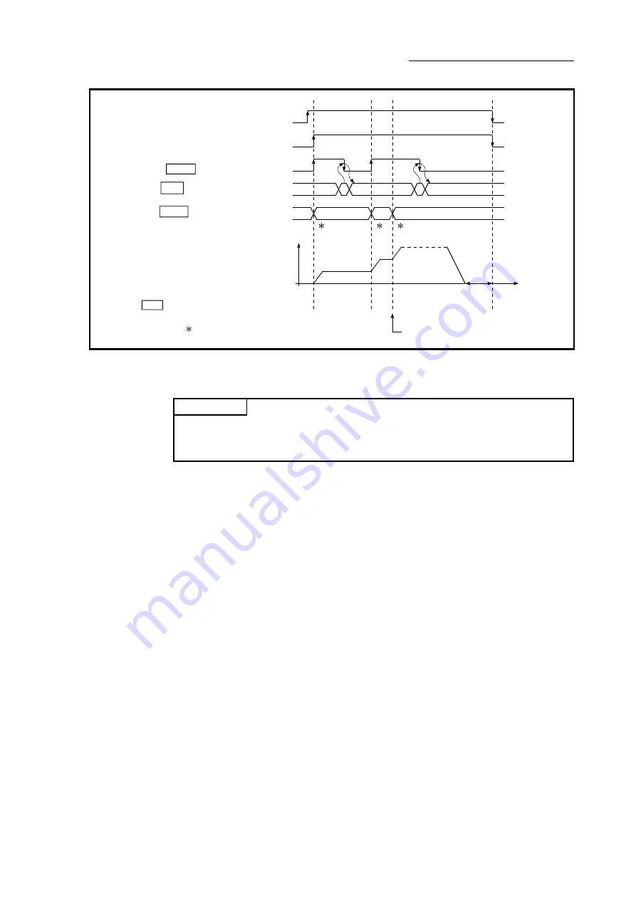
Fig. 13.42 Warning due to an M code ON signal during continuous path control
POINT
If the M code output function is not required, set a "0" in setting item "[Da.10] M
code /Condition data No./Number of LOOP to LEND repetitions" of the positioning
data.
[3] Precautions during control
(1) During interpolation control, the reference axis M code ON signal is turned
ON.
(2) The M code ON signal will not turn ON if "0" is set in "[Da.10] M
code/Condition data No./Number of LOOP to LEND repetitions". (The M
code will not be output, and the previously output value will be held in
"[Md.25] Valid M code".)
(3) If the M code ON signal is ON at the positioning start, the error "M code ON
signal start" (error code: 536) will occur, and the positioning will not start.
(4) If the PLC READY signal [Y0] is turned OFF, the M code ON signal will turn
OFF and "0" will be stored in "[Md.25] Valid M code".
(5) If the positioning operation time is short during continuous path control,
there will not be enough time to turn OFF the M code ON signal, and the
warning "M code ON signal ON" (warning code: 503) may occur. In this
case, set a "0" in the "[Da.10] M code/Condition data No./Number of LOOP
to LEND repetitions" of that section's positioning data.
(6) In the AFTER mode during speed control, the M code is not output and the
M code ON signal does not turn ON.
(7) If current value changing where "9003" has been set to "[Cd.3] Positioning
start No." is performed, the M code output function is made invalid.
Summary of Contents for MELSEC Q Series
Page 2: ......
Page 30: ...A 28 MEMO ...
Page 32: ...MEMO ...
Page 97: ...3 29 Chapter 3 Specifications and Functions MEMO ...
Page 102: ...3 34 Chapter 3 Specifications and Functions MEMO ...
Page 282: ...5 162 Chapter 5 Data Used for Positioning Control MEMO ...
Page 374: ...7 16 Chapter 7 Memory Configuration and Data Process MEMO ...
Page 376: ...MEMO ...
Page 400: ...8 24 Chapter 8 HPR Control MEMO ...
Page 425: ...9 25 Chapter 9 Major Positioning Control MEMO ...
Page 528: ...9 128 Chapter 9 Major Positioning Control MEMO ...
Page 554: ...10 26 Chapter 10 High Level Positioning Control MEMO ...
Page 586: ...11 32 Chapter 11 Manual Control MEMO ...
Page 800: ...16 54 Chapter 16 Troubleshooting MEMO ...
Page 830: ...Appendix 30 Appendices MEMO ...
Page 833: ......


