404
476671/B
Assigning functions to the rotary switches on
the Operating Panel .................................. 308
sonar room ................................................ 67
BITE (Built-In Test Equipment)
testing the receiver and transmitter channels
with the BITE B-Scan functionality ............... 319
testing the receiver and transmitter
channels................................................ 319
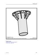
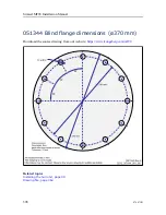
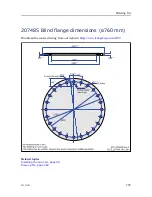
blind flange
outline dimensions............................... 398–399
backup ................................................... 333
Bottom reverberation....................................... 74
bridge
cable plan ............................................... 146
bridge units .................................................. 56
cable lengths.............................................. 57
maximum distance....................................... 57
testing the receiver and transmitter channels
with the BITE B-Scan functionality ............... 319
Setting up input from buoys, fish aggregating
devices and other external objects ................. 294
C
AC mains power cable (3-phase) to the Motor
Control Unit........................................... 176
Ethernet cable from Transceiver Unit to Motor
Control Unit........................................... 175
Ethernet cable RJ45 ............................. 173, 181
RS-232 serial line connection using five
wires.................................................... 166
RS-232 serial line connection using three
wires.................................................... 165
RS-232 used as synchronization trigger (input
or output) .............................................. 167
RS-422 serial line connection using five
wires.................................................... 168
sonar room .............................................. 150
prerequisites ............................................ 155
sonar room .............................................. 157
topside ................................................... 155
cable lengths................................................. 56
bridge units ............................................... 57
comments ............................................... 151
bridge .................................................... 146
comments ............................................... 151
sonar room .............................................. 150
topside ................................................... 146
Finalizing the cable connections..................... 224
installation (sonar room) .............................. 157
installation (topside)................................... 155
Making sure that all MF90 system cables are
properly connected ................................... 199
requirements .............................................. 36
sonar room .............................................. 151
topside ................................................... 148
CAT5
Ethernet cable .................................... 173, 181
CAT5E
Ethernet cable .................................... 173, 181
acoustic noise............................................. 71
hoisting (transducer)................................... 216
lowering (transducer).................................. 216
Checking the 3-phase connection for correct
rotation.................................................... 212
Checking the hosting motor’s 3-phase AC
connections............................................... 208
Checking the operation of the Hoisting and
Lowering contactors .................................... 214
Checking the transducer lowering and hoisting
functionality.............................................. 216
Choosing the best location for the Operating
Panel ........................................................ 60
approval ................................................... 38
approval (installation drawings) .............. 11,
classification society approval
requirements .............................................. 38
cable lists................................................ 151
cable plan ............................................... 151
description .............................................. 144
sonar room .............................................. 151
topside ................................................... 148
setting up the parameters ............................. 278
sonar room ................................................ 66
description ................................................ 29
required item ............................................. 29
scope of supply........................................... 29
requirements .............................................. 37
display ................................................... 361
Operating Panel .......................................... 60
technical specifications................................ 361
computer .................................................. 59
Hull Unit ................................................ 362
Operating Panel (Mk2)................................ 361
Operating Panel (Mk3)................................ 361
Processor Unit............................................ 59
transceiver .............................................. 362
Transceiver Unit ....................................... 362
audio output ............................................ 171
Choosing the best location for the Processor
Unit....................................................... 59
Compass Safe Distance (CSD)......................... 59
connectors............................................... 159
description ................................................ 21
installation .............................................. 130
introduction ............................................... 21
Moxa CP114EL-I Serial line adapter ............... 169
Simrad MF90 Installation Manual
Summary of Contents for Simrad MF90
Page 1: ...kongsberg com simrad Simrad MF90 INSTALLATION MANUAL...
Page 2: ......
Page 21: ...476671 B 19 Related topics Simrad MF90 page 13 Simrad MF90...
Page 369: ...476671 B 367 Drawing file...
Page 372: ...370 476671 B Simrad MF90 Installation Manual...
Page 375: ...476671 B 373 Drawing file...
Page 378: ...376 476671 B Simrad MF90 Installation Manual...
Page 384: ...382 476671 B Simrad MF90 Installation Manual...
Page 387: ...476671 B 385 Drawing file...
Page 390: ...388 476671 B Simrad MF90 Installation Manual...
Page 393: ...476671 B 391 Drawing file...
Page 398: ...396 476671 B Simrad MF90 Installation Manual...
Page 421: ......
Page 422: ...2022 Kongsberg Maritime ISBN 978 82 8066 240 8...
Page 423: ......
Page 425: ......
Page 426: ...Installation Manual Simrad MF90...


