124
476671/B
2
Make sure that the unit is not physically damaged, and that the surfaces and paint-work
are clean without dents or scratches.
The physical handling during the installation may have caused some minor scratches
to the surfaces or paint-work. This can be accepted. However, if rough handling has
caused serious damage, this must be recorded with a written statement and necessary
photos, so that corrective actions can be made.
3
Make sure that the physical installation of the unit has been completed.
a
Make sure that the welds and brackets used to support the hull unit are substantial
enough to hold the unit securely under all operating conditions.
b
Make sure that the compartment ("sonar room") in which the hull unit is mounted
is clean and dry.
c
Make sure that ample space is provided around the unit to allow for maintenance
and replacement of parts.
d
Make sure that all welds and brackets have been painted with the correct
preservation medium to prevent corrosion.
4
Make sure that cable installation has been completed.
a
Make sure that all cables leading to and from the unit have been properly mounted
and secured.
b
Make sure that the unit is securely connected to the ship's ground with an earthing
strap.
c
Make sure that enough slack has been provided on each cable to allow for
maintenance and replacement.
d
Make sure that the transducer cables can move freely when the transducer is
lowered and hoisted.
5
Make sure that there are no corrosive attacks on the hull unit, mounting flange,
installation trunk, support brackets or other parts of the installation.
6
Make sure that all relevant actions have been taken to reduce flow noise.
a
The hull plating in front of the transducer must be as smooth as possible.
Important
Be especially aware of bilge keels and sacrificial anodes. The keel must be
rounded off without sharp edges. Neither extruding objects nor abrupt transitions
must be present. Fill the space around any mounting bolts, as well as dents and
cracks in the plating, with a a suitable filling compound (putty).
b
The fairing around the installation trunk must be streamlined.
7
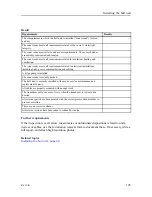
Fill in the result table.
Simrad MF90 Installation Manual
Summary of Contents for Simrad MF90
Page 1: ...kongsberg com simrad Simrad MF90 INSTALLATION MANUAL...
Page 2: ......
Page 21: ...476671 B 19 Related topics Simrad MF90 page 13 Simrad MF90...
Page 369: ...476671 B 367 Drawing file...
Page 372: ...370 476671 B Simrad MF90 Installation Manual...
Page 375: ...476671 B 373 Drawing file...
Page 378: ...376 476671 B Simrad MF90 Installation Manual...
Page 384: ...382 476671 B Simrad MF90 Installation Manual...
Page 387: ...476671 B 385 Drawing file...
Page 390: ...388 476671 B Simrad MF90 Installation Manual...
Page 393: ...476671 B 391 Drawing file...
Page 398: ...396 476671 B Simrad MF90 Installation Manual...
Page 421: ......
Page 422: ...2022 Kongsberg Maritime ISBN 978 82 8066 240 8...
Page 423: ......
Page 425: ......
Page 426: ...Installation Manual Simrad MF90...


