328
476671/B
this may cause a visible defect in the display presentation. If they are scattered, the
visible defect may be a lot harder to see. In all cases, the echoes from the neighbouring
channels cause an interpolation that will restore a lot of the degraded presentation.
Which actions to take if single channels fail depend on the operational impact, the
overall performance of the MF90 system, and a cost/benefit assessment. The most
important factor in the cost/benefit assessment is whether you need to replace the
transducer, or just a single transceiver board. If more than 3% of your transducer
elements have failed, we recommend that you contact your dealer for advice.
Note
For further investigations of this issue, use the functionality offered by the
Element
BITE
(Element Built In Test Equipment) dialog box.
10
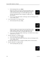
If the result from the reception test shows a number of transducer elements that are
either defective or offer reduced performance, repeat the test.
With the vessel in port, the environmental conditions are not satisfactory. In the shallow
waters of the port, noise from other vessels, dockyard workers or machinery will cause
unreliable test results. If you do this tests in a busy harbour, or with noise sources
present, the sensitive receivers will detect all the noise in the nearby waters. Excessive
noise or interference may be misinterpreted as physical defects.
You may need to repeat the test several times, and - if necessary - implement a "silent
ship" to improve the conditions.
11
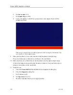
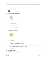
Finish the test.
a
Close the
Diagnostics
dialog box.
b
Set
Tx Power
to
Off
.
c
Hoist the transducer back up to its upper position.
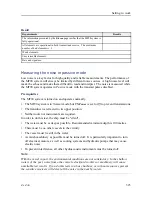
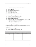
Result
Requirements
Results
The maximum number of bad elements is: 3
Date and signature:
Further requirements
If the noise level is higher than specified, you must check the reason(s) for this.
• Check the grounding of the Transceiver Unit.
• Verify that other electric equipment and/or machinery on board, such as cooling systems,
hydraulic pumps, electric motors etc, do not influence on the noise reading. Switch off as
much machinery as possible, especially electrical motors.
Simrad MF90 Installation Manual
Summary of Contents for Simrad MF90
Page 1: ...kongsberg com simrad Simrad MF90 INSTALLATION MANUAL...
Page 2: ......
Page 21: ...476671 B 19 Related topics Simrad MF90 page 13 Simrad MF90...
Page 369: ...476671 B 367 Drawing file...
Page 372: ...370 476671 B Simrad MF90 Installation Manual...
Page 375: ...476671 B 373 Drawing file...
Page 378: ...376 476671 B Simrad MF90 Installation Manual...
Page 384: ...382 476671 B Simrad MF90 Installation Manual...
Page 387: ...476671 B 385 Drawing file...
Page 390: ...388 476671 B Simrad MF90 Installation Manual...
Page 393: ...476671 B 391 Drawing file...
Page 398: ...396 476671 B Simrad MF90 Installation Manual...
Page 421: ......
Page 422: ...2022 Kongsberg Maritime ISBN 978 82 8066 240 8...
Page 423: ......
Page 425: ......
Page 426: ...Installation Manual Simrad MF90...

