266
476671/B
transducer is properly installed without unintentional skew, this angle can be
set to 0 degrees.
b
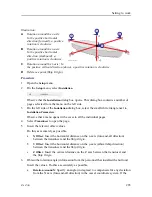
Rotation Around Y
: Specify an angle (in degrees) to compensate for any deviation
from the Y axis (athwartship direction) in the vessel coordinate system. If the
transducer is properly installed without unintentional skew, this angle can be
set to 0 degrees.
c
Rotation Around Z
: Specify an angle (in degrees) to compensate for any deviation
from the Z axis (vertical direction) in the vessel coordinate system. This is the
alignment angle.
• If the 0° transducer mark points to the starboard (right) side of the vessel’s
centre line, insert the alignment as a number between 0 and +180 degrees.
• If the 0° transducer mark points to the port (left) side of the vessel’s centre
line (as shown in the illustration), insert the alignment as a number between 0
and –180 degrees.
Examples:
• If the alignment angle is 120 degrees on the port side, insert -120 degrees.
• If the alignment angle is 15 degrees on the starboard side, insert 15 degrees.
7
At the bottom of the page, select
Apply
to save your settings.
8
Continue your work in the
Installation
dialog box, or select
OK
to close it.
Related topics
Setting to work, page 186
Inserting the installation parameters, page 259
Inserting the installation parameters for the motion reference
unit (MRU)
The physical rotation of the motion reference unit (MRU) relative to the transducer is
required to allow the MF90 system to adjust for roll and pitch as accurately as possible. This
task is only applicable is you are using an external motion reference unit on your MF90
system. Correct values for motion sensor rotation are critical for the sonar performance.
Prerequisites
The MF90 system hardware units are installed as specified in this manual.
• The MF90 system is turned on and operates normally.
• The MF90 system is in
Normal
mode, but
TX Power
is set to
Off
to prevent transmissions.
Simrad MF90 Installation Manual
Summary of Contents for Simrad MF90
Page 1: ...kongsberg com simrad Simrad MF90 INSTALLATION MANUAL...
Page 2: ......
Page 21: ...476671 B 19 Related topics Simrad MF90 page 13 Simrad MF90...
Page 369: ...476671 B 367 Drawing file...
Page 372: ...370 476671 B Simrad MF90 Installation Manual...
Page 375: ...476671 B 373 Drawing file...
Page 378: ...376 476671 B Simrad MF90 Installation Manual...
Page 384: ...382 476671 B Simrad MF90 Installation Manual...
Page 387: ...476671 B 385 Drawing file...
Page 390: ...388 476671 B Simrad MF90 Installation Manual...
Page 393: ...476671 B 391 Drawing file...
Page 398: ...396 476671 B Simrad MF90 Installation Manual...
Page 421: ......
Page 422: ...2022 Kongsberg Maritime ISBN 978 82 8066 240 8...
Page 423: ......
Page 425: ......
Page 426: ...Installation Manual Simrad MF90...

