104
476671/B
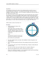
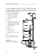
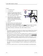
Hull unit installation example: Top view
The hull unit is located in the sonar room. This example shows a typical sonar room seen
from above.
A
Mechanical support brackets (Due
to its height and weight, the hull
unit gantry must be secured to the
bulkhead by means of mechanical
support brackets.)
B
Transducer cable
C
Transducer connector
D
Transceiver Unit
E
Forward
F
Strengthening knee plates (stifferen-
ers) (The location of strengthening
plates (stiffeners) on the installation
trunk is indicated. Minimum four
strengthening plates must be used.)
The installation trunk must be secured to
the bulkheads and/or the hull by means
of strengthening plates (stiffereners).
The dimensions and strength of the
plates must be adequate to prevent
any vibrations. This is an invariable
requirement to ensure the safety of the MF90 system and the vessel.
Stiffen the installation trunk in both the fore-and-aft and athwartship directions by welding
strengthening knee-plates both to the trunk and to the hull plating. The shape and locations
of the strengthening plates must be determined by the installation shipyard based on the
physical properties of the installation trunk, the hull and the space available. The minimum
plate thickness is 10 mm, but the classification society can specify other dimensions.
Due to its height and weight, the hull unit gantry must be secured to the bulkhead by means
of mechanical support brackets. The dimensions and strength of the support brackets must
be adequate to prevent vortex induced vibrations. This is an invariable requirement to ensure
the safety of the MF90 system and the vessel.
Note
It is the installation shipyard's responsibility that the installation trunk and the hull unit
gantry are properly secured against vibrations and sudden movements caused by the vessel's
behaviour in the sea.
Simrad MF90 Installation Manual
Summary of Contents for Simrad MF90
Page 1: ...kongsberg com simrad Simrad MF90 INSTALLATION MANUAL...
Page 2: ......
Page 21: ...476671 B 19 Related topics Simrad MF90 page 13 Simrad MF90...
Page 369: ...476671 B 367 Drawing file...
Page 372: ...370 476671 B Simrad MF90 Installation Manual...
Page 375: ...476671 B 373 Drawing file...
Page 378: ...376 476671 B Simrad MF90 Installation Manual...
Page 384: ...382 476671 B Simrad MF90 Installation Manual...
Page 387: ...476671 B 385 Drawing file...
Page 390: ...388 476671 B Simrad MF90 Installation Manual...
Page 393: ...476671 B 391 Drawing file...
Page 398: ...396 476671 B Simrad MF90 Installation Manual...
Page 421: ......
Page 422: ...2022 Kongsberg Maritime ISBN 978 82 8066 240 8...
Page 423: ......
Page 425: ......
Page 426: ...Installation Manual Simrad MF90...


