6
476671/B
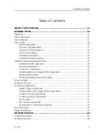
Location of the mounting brackets ............................................................................ 140
Installation of the mounting brackets ........................................................................ 141
Connecting the Transceiver Unit to vessel ground.................................................... 142
CABLE LAYOUT AND INTERCONNECTIONS............................... 143
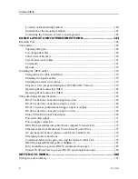
Read this first ...................................................................................................................... 144
Cable plans.......................................................................................................................... 145
Topside cable plan ..................................................................................................... 146
List of topside cables ................................................................................................. 148
Sonar room cable plan ............................................................................................... 150
List of sonar room cables .......................................................................................... 151
Comments.................................................................................................................. 151
Options ...................................................................................................................... 153
Prerequisites for cable installation ............................................................................ 155
Installing the topside cables ...................................................................................... 155
Installing the sonar room cables ................................................................................ 157
Processor Unit rear panel description: HT20470 (DC Version) ............................... 159
Operating Panel connectors (Mk2)............................................................................ 162
Operating Panel connectors (Mk3)............................................................................ 163
RS-232 serial line connection using three wires ....................................................... 165
RS-232 serial line connection using five wires ......................................................... 166
RS-232 used as synchronization trigger (input or output) ........................................ 167
RS-422 serial line connection using five wires ......................................................... 168
Moxa CP114EL-I Serial line adapter ........................................................................ 169
Powered audio output ................................................................................................ 171
Power supply connectors........................................................................................... 172
RJ45 High speed Ethernet cable (From computer to transceiver)............................. 173
Ethernet cable from Transceiver Unit to Motor Control Unit ................................... 175
AC mains power cable (3-phase) to the Motor Control Unit .................................... 176
Emergency hoist connections .................................................................................... 177
Connection between the gate valve and the Motor Control Unit .............................. 179
RJ45 High speed Ethernet cable (1000Base-t).......................................................... 181
K-Sync interface to generic RS-232 synchronization input ...................................... 182
Simrad TU40 interface to generic RS-232 synchronization input ............................ 184
SETTING TO WORK .................................................................. 186
Simrad MF90
Summary of Contents for Simrad MF90
Page 1: ...kongsberg com simrad Simrad MF90 INSTALLATION MANUAL...
Page 2: ......
Page 21: ...476671 B 19 Related topics Simrad MF90 page 13 Simrad MF90...
Page 369: ...476671 B 367 Drawing file...
Page 372: ...370 476671 B Simrad MF90 Installation Manual...
Page 375: ...476671 B 373 Drawing file...
Page 378: ...376 476671 B Simrad MF90 Installation Manual...
Page 384: ...382 476671 B Simrad MF90 Installation Manual...
Page 387: ...476671 B 385 Drawing file...
Page 390: ...388 476671 B Simrad MF90 Installation Manual...
Page 393: ...476671 B 391 Drawing file...
Page 398: ...396 476671 B Simrad MF90 Installation Manual...
Page 421: ......
Page 422: ...2022 Kongsberg Maritime ISBN 978 82 8066 240 8...
Page 423: ......
Page 425: ......
Page 426: ...Installation Manual Simrad MF90...

