476671/B
95
Important
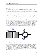
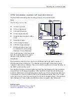
To obtain optimal MF90 system performance, the total height of the installation trunk
must be as close as possible to its stated minimum height.
The top flange must be parallel to the water line in both the fore-and-aft and athwartship
directions.
6
Make sure that the upper surface of the installation trunk is level, undamaged and clean.
7
Cover the upper surface of the installation trunk with a blind flange or wooden plate to
protect it.
8
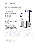
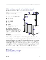
Brace the installation trunk to the hull plating and the surrounding hull frames by
adding several strengthening plates.
The dimensions and strength of the plates must be adequate to prevent any vibrations.
The shape and locations of the strengthening plates must be determined by the
installation shipyard based on the physical properties of the installation trunk, the
hull and the space available. Minimum four strengthening plates must be used. Each
strengthening plate must extend all the way from the bottom to the top of the installation
trunk. Only leave a small gap to allow access to the bolts and nuts used to secure the
mounting flange. The minimum plate thickness is 10 mm, but the classification society
can specify other dimensions.
9
Depending on the shape of the hull, we recommend that you fit a steel blister for
protection.
The blister must be designed by the installation shipyard. It must be welded to the
shell plating. The blister may be an open type, or it can be filled with oil to prevent
corrosion. This last method provides excellent protection, and simplifies maintenance.
Note
Make sure that the hull plating surrounding the trunk is even and smooth without
protruding objects that can cause noise. Objects protruding from the hull will generate
turbulence and flow noise. This will reduce the overall performance of your system. If
necessary, grind and polish all surfaces.
10
As soon as all installation, welding and grinding has been done, prime or paint the trunk
and the surrounding area using a high quality protective coating.
Note
You must also apply the protective coating to the inside of the installation trunk.
11
Inspect the installation of the installation trunk, the blister, hull plating and all surfaces
thoroughly.
Summary of Contents for Simrad MF90
Page 1: ...kongsberg com simrad Simrad MF90 INSTALLATION MANUAL...
Page 2: ......
Page 21: ...476671 B 19 Related topics Simrad MF90 page 13 Simrad MF90...
Page 369: ...476671 B 367 Drawing file...
Page 372: ...370 476671 B Simrad MF90 Installation Manual...
Page 375: ...476671 B 373 Drawing file...
Page 378: ...376 476671 B Simrad MF90 Installation Manual...
Page 384: ...382 476671 B Simrad MF90 Installation Manual...
Page 387: ...476671 B 385 Drawing file...
Page 390: ...388 476671 B Simrad MF90 Installation Manual...
Page 393: ...476671 B 391 Drawing file...
Page 398: ...396 476671 B Simrad MF90 Installation Manual...
Page 421: ......
Page 422: ...2022 Kongsberg Maritime ISBN 978 82 8066 240 8...
Page 423: ......
Page 425: ......
Page 426: ...Installation Manual Simrad MF90...

