406
476671/B
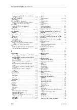
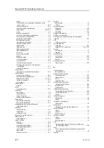
flow noise ................................................. 71
Global Positioning System (GPS) ..................... 31
gyro compass ............................................. 29
heading sensor............................................ 29
hull unit ............................... 109–110, 204–205
Hull Unit ............................................ 23, 201
hull unit installation ................................... 100
installation close to echo sounder
transducer(s) ............................................ 54
installation trunk ......................................... 28
Installation trunk ......................................... 26
installation with more than one hull unit ............. 53
interconnection cables................................. 144
interference ............................................... 72
machinery noise.......................................... 70
mechanical support brackets ......................... 101
Motor Control Unit .................................... 206
Moxa CP114EL-I Serial line adapter ............... 169
O-ring................................................ 80, 102
Operating Panel .......................................... 30
Processor Unit............................................ 21
propellers.................................................. 71
rattle noise ................................................ 72
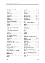
RS-232 serial line connection using five
wires.................................................... 166
RS-232 serial line connection using three
wires.................................................... 165
RS-232 used as synchronization trigger (input
or output) .............................................. 167
RS-422 serial line connection using five
wires.................................................... 168
rubber gasket ....................................... 80, 102
self noise .................................................. 70
shipyard cables ......................................... 144
software backup........................................ 333
speed log .................................................. 29
strengthening knee plate (stifferener) ................. 81
support brackets........................................ 101
system ..................................................... 16
system cables ........................................... 144
Transceiver Unit ......................................... 22
Transducer ................................................ 25
uninterruptible power supply........................... 30
UPS ........................................................ 30
vessel coordinate system.............................. 256
vessel coordinate system alternative origin ........ 256
vessel coordinate system origin...................... 256
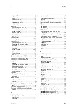
reverberation.............................................. 74
support brackets........................................ 119
Designing and mounting mechanical support
brackets to secure the hull unit ........................ 119
backup ................................................... 334
Verifying system operation by means of the
Diagnostics functionality............................ 325
system ..................................................... 18
description .............................................. 251
Surveying the transducer and the navigation
sensors ................................................. 253
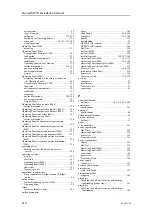
dimensions
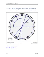
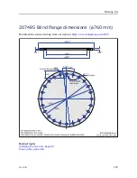
blind flange ....................................... 398–399
computer .......................................... 366, 369
display ................................................... 355
HT20470 (AC version)................................ 369
HT20470 (DC version)................................ 366
Hull Unit ................................................ 356
hull unit MF90 ......................................... 384
hull unit MF94 ......................................... 387
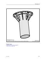
installation trunk ........................... 390, 393, 395
Operating Panel (Mk2).......................... 355, 375
Operating Panel (Mk3).......................... 356, 381
Operating Panel adapter plate (Mk2)................ 379
Operating Panel cut
out (Mk2) ...................... 378
Processor Unit.................................... 366, 369
technical specifications................................ 355
transceiver .............................................. 356
Transceiver Unit ................................. 356, 372
Choosing the best location for the display............ 59
compass safe distance ................................. 361
description ................................................ 20
dimensions .............................................. 355
display ................................................... 189
environmental requirements.......................... 358
installation .............................................. 129
minimum requirements ............................... 362
outline dimensions..................................... 355
power requirements.................................... 352
weight ................................................... 355
requirements .............................................. 38
downloading .............................................. 11
documentation............................................ 11
installation drawings .................................... 47
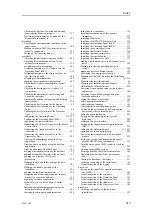
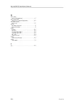
AC mains power cable (3-phase) to the Motor
Control Unit........................................... 176
blind flange ....................................... 398–399
computer .......................................... 366, 369
display outline dimensions ........................... 355
Ethernet cable from Transceiver Unit to Motor
Control Unit........................................... 175
Ethernet cable RJ45 ............................. 173, 181
HT20470 (AC version)................................ 369
HT20470 (DC version)................................ 366
hull unit MF90 ......................................... 384
hull unit MF94 ......................................... 387
installation trunk ........................... 390, 393, 395
Operating Panel (Mk2)................................ 375
Operating Panel (Mk3)................................ 381
Operating Panel adapter plate (Mk2)................ 379
Operating Panel cut
out (Mk2) ...................... 378
Processor Unit.................................... 366, 369
RS-232 serial line connection using five
wires.................................................... 166
RS-232 serial line connection using three
wires.................................................... 165
RS-232 used as synchronization trigger (input
or output) .............................................. 167
RS-422 serial line connection using five
wires.................................................... 168
Transceiver Unit ....................................... 372
Simrad MF90 Installation Manual
Summary of Contents for Simrad MF90
Page 1: ...kongsberg com simrad Simrad MF90 INSTALLATION MANUAL...
Page 2: ......
Page 21: ...476671 B 19 Related topics Simrad MF90 page 13 Simrad MF90...
Page 369: ...476671 B 367 Drawing file...
Page 372: ...370 476671 B Simrad MF90 Installation Manual...
Page 375: ...476671 B 373 Drawing file...
Page 378: ...376 476671 B Simrad MF90 Installation Manual...
Page 384: ...382 476671 B Simrad MF90 Installation Manual...
Page 387: ...476671 B 385 Drawing file...
Page 390: ...388 476671 B Simrad MF90 Installation Manual...
Page 393: ...476671 B 391 Drawing file...
Page 398: ...396 476671 B Simrad MF90 Installation Manual...
Page 421: ......
Page 422: ...2022 Kongsberg Maritime ISBN 978 82 8066 240 8...
Page 423: ......
Page 425: ......
Page 426: ...Installation Manual Simrad MF90...


