18
476671/B
System diagram
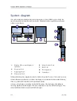
The system diagram identifies the main components of a basic MF90 system. Only the
main connections between the units are shown. Detailed interface capabilities and power
cables are not shown.
A
Display (The second display is
optional.)
B
Processor Unit
C
Operating Panel
D
Transceiver Unit
E
Motor Control Unit
F
Hull Unit
G
Hoisting motor
H
Transducer
In this publication, the computer can also be referred to as the
Processor Unit
, and vice versa.
Unless otherwise specified in a contract, the display is not included in the standard delivery.
This is a commercial item that can be purchased locally.
A choice of hull units is available for the MF90 system. The hull units offer different
lowering depths and cable lengths. The same transducer is used on all hull unit types. The
same installation trunk is used on all hull unit types.
Simrad MF90 Installation Manual
Summary of Contents for Simrad MF90
Page 1: ...kongsberg com simrad Simrad MF90 INSTALLATION MANUAL...
Page 2: ......
Page 21: ...476671 B 19 Related topics Simrad MF90 page 13 Simrad MF90...
Page 369: ...476671 B 367 Drawing file...
Page 372: ...370 476671 B Simrad MF90 Installation Manual...
Page 375: ...476671 B 373 Drawing file...
Page 378: ...376 476671 B Simrad MF90 Installation Manual...
Page 384: ...382 476671 B Simrad MF90 Installation Manual...
Page 387: ...476671 B 385 Drawing file...
Page 390: ...388 476671 B Simrad MF90 Installation Manual...
Page 393: ...476671 B 391 Drawing file...
Page 398: ...396 476671 B Simrad MF90 Installation Manual...
Page 421: ......
Page 422: ...2022 Kongsberg Maritime ISBN 978 82 8066 240 8...
Page 423: ......
Page 425: ......
Page 426: ...Installation Manual Simrad MF90...


