256
476671/B
d
Measure the horizontal distance in parallel with the Y axis from the origin to
the sensor.
The sensor is on the port side of the centre line while the origin is located on the
starboard side. This is the Y value. The value is
negative
because the sensor is
located on the
port
side of the origin.
e
Type the values you have found for X, Y and Z into the
Sensor Installation
page
when you install the sensor in the MF90 user interface.
4
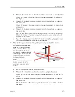
Measure the physical location of the motion reference unit (MRU).
The motion reference unit is located next to the sonar hull unit. Both are placed on the
vessel’s centre line and close to the bow.
a
Draw a vertical line from the sensor and up.
b
Measure the vertical distance from the waterline and down to the sensor.
This is the Z value. The value is
positive
because the sensor is located
under
the origin.
c
Measure the horizontal distance in parallel with the X axis from the origin to
the vertical line.
This is the X value. The value is
positive
because the sensor is located
in front
of
the origin.
d
Measure the horizontal distance in parallel with the Y axis from the origin to
the centre line.
The sensor is on the centre line, but the origin is located on the starboard side.
This is the Y value. The value is
negative
because the sensor is located on the
port
side of the origin.
e
Type the values you have found for X, Y and Z into the
Sensor Installation
page
when you install the sensor in the MF90 user interface.
Related topics
Setting to work, page 186
Placing each sensor in the vessel coordinate system, page 251
Vessel coordinate system, page 256
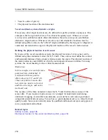
Vessel coordinate system
The vessel coordinate system is established to define the relative physical locations of
system units and sensors.
When you have several different sensors and transducers on your vessel, and you wish each
of them to provide accurate data, you need to know their relative physical positions. The
Simrad MF90 Installation Manual
Summary of Contents for Simrad MF90
Page 1: ...kongsberg com simrad Simrad MF90 INSTALLATION MANUAL...
Page 2: ......
Page 21: ...476671 B 19 Related topics Simrad MF90 page 13 Simrad MF90...
Page 369: ...476671 B 367 Drawing file...
Page 372: ...370 476671 B Simrad MF90 Installation Manual...
Page 375: ...476671 B 373 Drawing file...
Page 378: ...376 476671 B Simrad MF90 Installation Manual...
Page 384: ...382 476671 B Simrad MF90 Installation Manual...
Page 387: ...476671 B 385 Drawing file...
Page 390: ...388 476671 B Simrad MF90 Installation Manual...
Page 393: ...476671 B 391 Drawing file...
Page 398: ...396 476671 B Simrad MF90 Installation Manual...
Page 421: ......
Page 422: ...2022 Kongsberg Maritime ISBN 978 82 8066 240 8...
Page 423: ......
Page 425: ......
Page 426: ...Installation Manual Simrad MF90...


