286
476671/B
7
If you want to check the communication parameters, select
Inspect Port
.
Note
You cannot make any changes here. To change the communication parameters, use
the
I/O Setup
page.
8
If you want to check that the peripheral system is transmitting data to the MF90 system,
select
Monitor
.
The
Port Monitor
dialog box provides one text box for incoming messages (
Rx Data
),
and one for outgoing messages (
Tx Data
). Use these boxes and your knowledge of the
data communication to investigate the datagrams. The
Port Monitor
dialog box is a
tool for debugging purposes. It is neither required nor intended for normal operation of
the MF90 system.
9
Type a custom name to identify the interface in other dialog boxes.
10
Select which datagram(s) you want to import from the sensor.
11
If relevant, specify a dedicated talker ID.
12
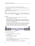
Provide the accurate physical location of the sensor (or its antenna) with reference to
the vessel’s coordinate system.
The position of certain sensors must be defined as an
offset
to the
Ship Origin
in the
coordinate system to maximize performance. These offset values are all required to
allow the MF90 system to give you as accurate information as possible. The degree
of accuracy offered by the MF90 system is directly related to the accuracy of the
information you enter on the
Sensor Installation
page.
a
Select the offset value on the X axis (fore-and-aft direction) from the
Ship Origin
.
Adjust with a positive value for X if the sensor is located ahead of the ship origin.
b
Select the offset value on the Y axis (athwartship) from the
Ship Origin
. Adjust
with a positive value for Y if the sensor is located on the starboard side of the
ship origin.
c
Select the offset value on the Z axis (vertical) from the
Ship Origin
. Adjust with a
positive value for Z if the sensor is located under the ship origin.
13
Select
Add
to save the new sensor interface you have defined.
The sensor interface is added to the
Installed Sensors
list on the
Sensor Installation
page.
14
At the bottom of the dialog box, select
Apply
to save your settings.
15
Continue your work in the
Installation
dialog box, or select
OK
to close it.
Simrad MF90 Installation Manual
Summary of Contents for Simrad MF90
Page 1: ...kongsberg com simrad Simrad MF90 INSTALLATION MANUAL...
Page 2: ......
Page 21: ...476671 B 19 Related topics Simrad MF90 page 13 Simrad MF90...
Page 369: ...476671 B 367 Drawing file...
Page 372: ...370 476671 B Simrad MF90 Installation Manual...
Page 375: ...476671 B 373 Drawing file...
Page 378: ...376 476671 B Simrad MF90 Installation Manual...
Page 384: ...382 476671 B Simrad MF90 Installation Manual...
Page 387: ...476671 B 385 Drawing file...
Page 390: ...388 476671 B Simrad MF90 Installation Manual...
Page 393: ...476671 B 391 Drawing file...
Page 398: ...396 476671 B Simrad MF90 Installation Manual...
Page 421: ......
Page 422: ...2022 Kongsberg Maritime ISBN 978 82 8066 240 8...
Page 423: ......
Page 425: ......
Page 426: ...Installation Manual Simrad MF90...


