


22
476671/B
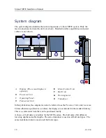
Transceiver Unit description
The Transceiver Unit is provided to transmit acoustic energy through water. After each
transmission, the transceiver receives the echoes from the seabed and/or the water column.
These echoes are filtered, amplified and finally converted into digital format. This
transmission and reception sequence is commonly referred to as a
ping
.
The Transceiver Unit is normally located in the sonar room. It is mounted on the bulkhead
using powerful shock absorbers. The physical distance to the hull unit is limited by the
length of the transducer cables.
The transceiver controls the transmission and reception made by the transmitters and
receiver channels. 16 identical transceiver boards are used. These transceiver boards
provide 480 individual transmit- and receiver channels. The Transceiver Unit also holds an
Ethernet switch and a large capacitor bank. An internal power supply is provided to supply
the required DC voltages to the Transceiver Unit.
A high quality Ethernet cable is used for communication with the Processor Unit on the
bridge. Another high quality Ethernet cable is used to connect the Transceiver Unit to the
Motor Control Unit on the hull unit.
It is very important that high-quality Ethernet cables are used. Do not make the connection
using the existing local area network (LAN).
Tip
We recommend that you install an extra Ethernet cable between the Transceiver Unit and
the Processor Unit.
The transducer cables are plugged into the side wall of the transceiver cabinet using a special
connector. The connectors for power and interfaces are located at the bottom of the cabinet.
Note
To extend the lifetime of the Transceiver Unit, it must be mounted at dry and clean location
with sufficient ventilation. Observe the sonar room requirements
The Transceiver Unit can be fitted with a commercial heat exchanger. The purpose of the
heat exchanger is to provide a stable, clean and temperature controlled environment for
the electronic circuitry inside the Transceiver Unit. The heat exchanger also inhibits dust
and dirt particles from entering the transceiver. The heat exchanger is powered from 230
VAC using a separate outlet.
Simrad MF90 Installation Manual
Summary of Contents for Simrad MF90
Page 1: ...kongsberg com simrad Simrad MF90 INSTALLATION MANUAL...
Page 2: ......
Page 21: ...476671 B 19 Related topics Simrad MF90 page 13 Simrad MF90...
Page 369: ...476671 B 367 Drawing file...
Page 372: ...370 476671 B Simrad MF90 Installation Manual...
Page 375: ...476671 B 373 Drawing file...
Page 378: ...376 476671 B Simrad MF90 Installation Manual...
Page 384: ...382 476671 B Simrad MF90 Installation Manual...
Page 387: ...476671 B 385 Drawing file...
Page 390: ...388 476671 B Simrad MF90 Installation Manual...
Page 393: ...476671 B 391 Drawing file...
Page 398: ...396 476671 B Simrad MF90 Installation Manual...
Page 421: ......
Page 422: ...2022 Kongsberg Maritime ISBN 978 82 8066 240 8...
Page 423: ......
Page 425: ......
Page 426: ...Installation Manual Simrad MF90...


