232
[3] Positioning [Basic] (ST0 to ST2, LS0 to LS1)
Position No.
Input
Output
0
ST0
LS0
1
ST1
LS1
2
ST2
LS2
(Note) Pressing and pitch feed are unavailable.
Sample use
No.
Position
[mm]
Velocity
[mm/s]
Accele-
ration
[G]
Decele-
ration
[G]
Pressing
[%]
Thresh-
old
[%]
Positioning
width
[mm]
Zone+
[mm]
Zone-
[mm]
Acceleration/
Deceleration
mode
Incre-
mental
Gain
set
Stop
mode
0
0.00
100.00
0.20
0.20
0
0
0.10
0.00
0.00
0
0
0
0
1
70.00
100.00
0.20
0.20
0
0
0.10
0.00
0.00
0
0
0
0
2
150.00
200.00
0.20
0.20
0
0
0.10
0.00
0.00
0
0
0
0
Control method
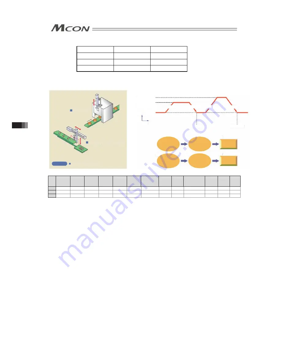
1) When start signal ST* is turned ON, the actuator starts acceleration based on the data in
the specified position table for positioning to the target position. Turning the ST* signal
OFF on the way causes the actuator to be decelerated and stopped. So, make the ST*
signal remain ON until the actuator reaches the target position.
2) At the completion of positioning, position detection output LS* of the specified position is
turned ON.
3) Position detection output LS* is turned ON if the remaining moving distance enters into
the positioning width. LS* is set to ON if the current position is located within the
positioning width zone or OFF if the current position is located out of the positioning width
zone (the same situation occurs in the servo OFF status).
4) Leave the ST* signal to be ON until the actuator is moved to another position and turn
OFF it at the next ST* signal. If the ST* signal is turned OFF at the LS* signal, the
actuator is decelerated to a stop in the positioning width and thus the actuator may not
reach the target position. In continuous operation, turn ON the next ST* signal by setting
the positioning width within the required precision range or setting the period taken from
detection of the LS* signal to reaching the target position.
Used for door
open/close
Used for pick & place unit
Work carriage, movement, etc
Usage
Deceleration
Position 1
Acceleration
2)
3)
1)
4)
5)
Acceleration
Deceleration
Position 2
6)
2) 3)
1)
4)
5) 6)
200mm/sec
100mm/sec
Input start signal
to Position No.1
(Moving start)
Moving
comp.
Positioning
complete signal
of position 1
output
Stop
status
Velocity
Time
Input start signal
to Position No.2
(Moving start)
Moving
comp.
Positioning
complete signal
of position 2
output
3.8 Control and functions of Input and output signals of Remote I/O Mode
Summary of Contents for MCON-C
Page 1: ...MCON C CG Controller Instruction Manual Fourth Edition ...
Page 2: ......
Page 48: ...38 Chapter 1 Specifications Check ...
Page 268: ...258 3 10 Fieldbus Status LEDs ...
Page 274: ...264 Chapter 4 Vibration Suppress Control Function ...
Page 278: ...268 Chapter 5 Collision Detection Feature ...
Page 284: ...274 Chapter 6 Power saving Function ...
Page 292: ...282 Chapter 7 Absolute Reset and Absolute Battery ...
Page 358: ...348 Chapter 9 Troubleshooting ...
Page 474: ...Chapter 10 Appendix 464 ...
Page 478: ......
Page 479: ......


