


219
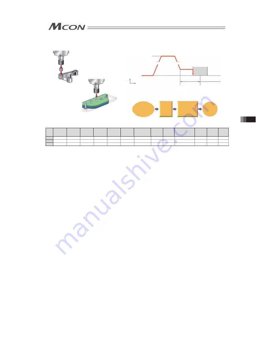
[3] Pressing operation
Sample use
No.
Position
[mm]
Velocity
[mm/s]
Accele-
ration
[G]
Decele-
ration
[G]
Pressing
[%]
Thresh-
old
[%]
Positioning
width
[mm]
Zone+
[mm]
Zone-
[mm]
Acceleration/
Deceleration
mode
Incre-
mental
Gain
set
Stop
mode
0
1
0.00
250.00
0.20
0.20
0
0
0.10
0.00
0.00
0
0
0
0
2
100.00
250.00
0.20
0.20
50
0
50.00
0.00
0.00
0
0
0
0
(Position No.2 sets pressing operation.)
Control method
1) The method of controlling the pressing operation is the same as that described in [1]
Positioning except the setting of the position table. Any setting of “Pressing” in the
position table allows the pressing operation to be done. “Positioning width” is assumed as
pressing operation distance.
2) The actuator moves at the setting speed and rating torque to the position of the
coordinate set in “Position” in the similar way as normal positioning. Then the operation
changes to pressing. The moving distance in pressing is the value set in “Positioning
width”. The pressing is performed with the torque (current limit value) set in percent in
“Pressing” of PIO patterns 4 being the upper limit.
Pressing operation using force sensor of PIO pattern 7 performs pressing by the pressing
force set in percent of the base thrust in pressing operation using force sensor
*1
.
3) The control method is the same as that in [1] Positioning. However, the processing of
positioning complete signal PEND is different from that in [1] Positioning.
PEND is output when the shaft is stopped by pressing (pressing complete). If the work is
not subject to pressing (miss-pressing), the actuator moves by the value set in
“Positioning width” to stop but PEND is not turned ON. The current position No. PE* is
turned ON at the completion of pressing and even in miss-pressing.
Press-fitting process
Caulking process
2)
1)
Start signal input
for position No.2
(Moving start)
Move
forwarc at
low speed
without stop
Pressing to work
and stop
Pressing held by
setup pressing force
Positioning
Completion
2)
3)
4)
1)
Position 1
Coordinate
Value:100
3) 4)
Positioning width 50
250mm/sec
Without contaction work
until the end of
positioning band,
positioning complete
signal is not output
Work
Stop
status
Acceleration
Deceleration
Velocity
Time
3.8 Control and functions of Input and output signals of Remote I/O Mode
Summary of Contents for MCON-C
Page 1: ...MCON C CG Controller Instruction Manual Fourth Edition ...
Page 2: ......
Page 48: ...38 Chapter 1 Specifications Check ...
Page 268: ...258 3 10 Fieldbus Status LEDs ...
Page 274: ...264 Chapter 4 Vibration Suppress Control Function ...
Page 278: ...268 Chapter 5 Collision Detection Feature ...
Page 284: ...274 Chapter 6 Power saving Function ...
Page 292: ...282 Chapter 7 Absolute Reset and Absolute Battery ...
Page 358: ...348 Chapter 9 Troubleshooting ...
Page 474: ...Chapter 10 Appendix 464 ...
Page 478: ......
Page 479: ......