84
3.4 Fieldbus Type Address Map
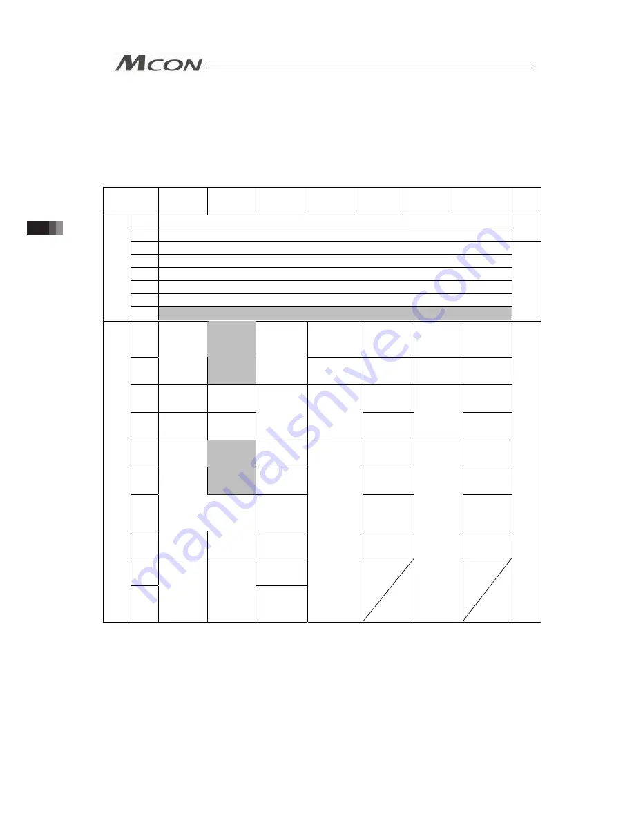
3.4.1 PLC Address Construction by each Operation Mode
The address domain to be occupied differs depending on the operation mode.
Refer to the example in Section 3.4.2 for the assignment.
y
PLC Output → MCON Input (n is PLC output top word address to MCON)
(Note 1)
PLC output
Area
Simple
Direct
Mode
Positioner 1
Mode
Direct
Indication
Mode
Positioner 2
Mode
Positioner 3
Mode
Positioner 5
Mode
Remote I/O
Mode
Details
n
Gateway Control 0
n+1
Gateway Control 1
3.4.3
n+2
Demand Command
n+3
Data 0
n+4
Data 1
n+5
Data 2
n+6
Data 3
MCON
G
ate
way
Control
Area
n+7
Occupied Area
(Note 2)
3.4.11
n+8
Specified
Position No.
(Axis No.0)
Control
Signal/
Position No.
(Axis No.0)
Specified
Position No.
(Axis No.0)
Assignment
Area for
Axis No.0
n+9
Target
Position
(Axis No.0)
Occupied
Area
(Note 2)
Target
Position
(Axis No.0)
Control Signal
(Axis No.0)
Assignment
Area for
Axis No.1
Control
Signal
(Axis No.0)
Assignment
Area for
Axis No.1
n+10
Specified
Position No.
(Axis No.0)
Specified
Position No.
(Axis No.0)
Assignment
Area for
Axis No.2
Assignment
Area for
Axis No.2
n+11
Control
Signal
(Axis No.0)
Control
Signal
(Axis No.0)
Positioning
Width
(Axis No.0)
Assignment
Area for
Axis No.1
Assignment
Area for
Axis No.3
Assignment
Area for
Axis No.1 Assignment
Area for
Axis No.3
n+12
Velocity
(Axis No.0)
Assignment
Area for
Axis No.4
Assignment
Area for
Axis No.4
n+13
Occupied
Area
(Note 2)
Acceleration/
Deceleration
(Axis No.0)
Assignment
Area for
Axis No.5
Assignment
Area for
Axis No.5
n+14
Current
Limitation
Value
(Axis No.0)
Assignment
Area for
Axis No.6
Assignment
Area for
Axis No.6
n+15
Assignment
Area for
Axis No.1
Assignment
Area for
Axis No.1
Control
Signal
(Axis No.0)
Assignment
Area for
Axis No.7
Assignment
Area for
Axis No.7
n+16
to
n+23
Assignment
Area for
Axis No.1
Connected
Axes Control
Area
n+24
to
n+71
Assignment
Area for
Axis No.2
and later
Assignment
Area for
Axis No.2
and later
Assignment
Area for
Axis No.2
and later
Assignment
Area for
Axis No.2
and later
Assignment
Area for
Axis No.2
and later
3.4.4
to
3.4.10
Note 1 For CC-Link and CC-Link IE Field, from n to n+7 should be the bit address for
MCON input and n+8 should be the top address of the data register.
Note 2 This is the domain occupied unconditionally. Therefore, this domain cannot be used
for any other purpose.
3.4 Fieldbus
Type
Address Map
Summary of Contents for MCON-C
Page 1: ...MCON C CG Controller Instruction Manual Fourth Edition ...
Page 2: ......
Page 48: ...38 Chapter 1 Specifications Check ...
Page 268: ...258 3 10 Fieldbus Status LEDs ...
Page 274: ...264 Chapter 4 Vibration Suppress Control Function ...
Page 278: ...268 Chapter 5 Collision Detection Feature ...
Page 284: ...274 Chapter 6 Power saving Function ...
Page 292: ...282 Chapter 7 Absolute Reset and Absolute Battery ...
Page 358: ...348 Chapter 9 Troubleshooting ...
Page 474: ...Chapter 10 Appendix 464 ...
Page 478: ......
Page 479: ......


