background image

ASDA-B2 

Chapter 6  Control Modes of Operation 

Revision May, 2018 


6-7 

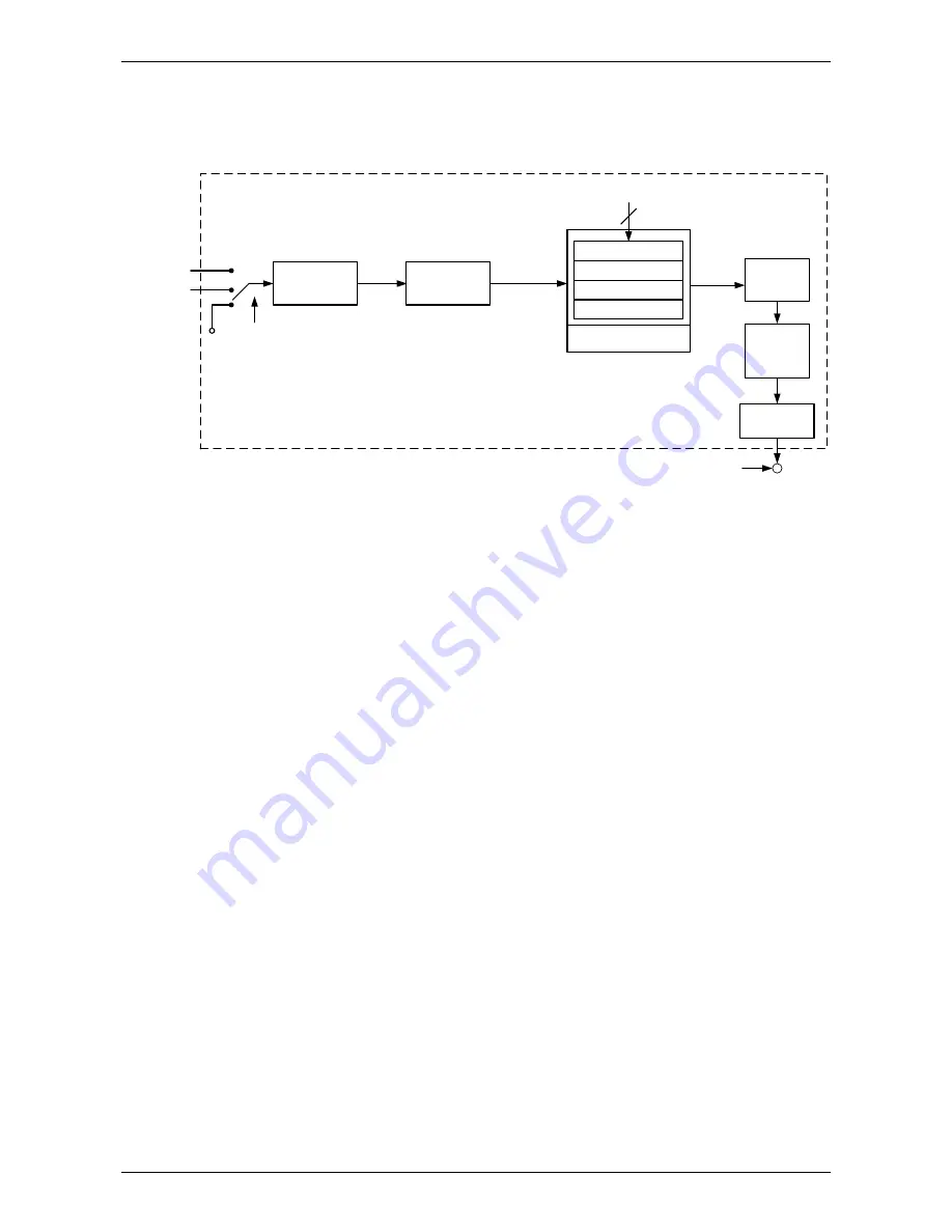
For a better control, the pulse signal should be processed and modified through position 
command unit. Structure is shown as the diagram below. 

Pulse Signal

Counter

1

st

 Numerator (P1-44)

2

nd

 Numerator (P2-60)

3

rd

 Numerator (P2-61)

4

th

 Numerator (P2-62)

Denominator (P1-45)

GNUM0, GNUM1

High speed

Low speed

INHIBIT

Pulse Type 

Selection

P1-00

Command 

Selection

P1-01

Moving 

Filter

P1-68

Low-pass 

Filter

P1-08

Position Command 

Processing Unit


PT mode which is shown in the figure can be selected via P1-01. It can set E-gear ratio for 
the proper position resolution. Moreover, either S-curve filter or low-pass filter can be used 
to smooth the command. See the description in later parts. 


Pulse Command Inhibit Input Function (INHP) 

Use DI to select INHP (Refer to P2-10~17, P2-36 and table 7.1 INHP (45)) before using 
this function. If not, this function will be unable to use. When DI (INHP) is ON, the pulse 
command will be cleared in position control mode and the motor will stop running.


Summary of Contents for ASD-B2-1521-F

Page 1: ......

Page 2: ...read through this manual carefully in order to ensure the correct use of the product In addition please place this manual safely for quick reference whenever is needed Please follow the rules below i...

Page 3: ...in the environment which complies with the minimum requirement of UL Level 1 or NEMA 250 Type 1 Pay special attention to the following safety precautions anytime during inspection installation wiring...

Page 4: ...tial trial run If users fail to operate the machine properly after the servo motor connects to the equipment it would cause the damage of the equipment and lead to the personnel injury In order to pre...

Page 5: ...off Do not touch the power terminal temporally at least 10 minutes Please conduct the inspection not until the indicator light CHARGE is off Do not turn the power on and off too often If continuous p...

Page 6: ...1 Notes 2 1 2 2 Ambient Conditions of Storage 2 1 2 3 Ambient Conditions of Installation 2 2 2 4 Installation Direction and Space 2 3 2 4 1 Troubleshooting for the Motor Operation and Status 2 5 2 4 2...

Page 7: ...6 3 1 5 Specification of Encoder Connector 3 8 3 1 6 Selection of Wiring Rod 3 12 3 2 Basic Wiring 3 14 3 2 1 200 W included and Models below 3 14 3 2 2 400 W 750 W Models 3 15 3 2 3 1 kW 3 kW Models...

Page 8: ...3 4 3 1 Save Setting Display 4 3 4 3 2 Decimal Point 4 3 4 3 3 Alarm Message 4 3 4 3 4 Positive and Negative Sign Setting 4 4 4 3 5 Monitor Display 4 4 4 4 General Function 4 7 4 4 1 Operation of Fau...

Page 9: ...ppression Method 5 17 5 5 7 Tuning Modes and Parameters 5 18 5 5 8 Tuning in Manual Mode 5 19 Chapter 6 Control Modes of Operation 6 1 6 1 Selection of Operation Mode 6 1 6 2 Position Mode 6 3 6 2 1 P...

Page 10: ...8 6 4 4 The Scaling of Analog Command 6 38 6 4 5 Timing Diagram of Torque Mode 6 40 6 5 Dual Modes 6 41 6 5 1 Speed Position Dual Mode 6 41 6 5 2 Speed Torque Dual Mode 6 42 6 5 3 Torque Position Dual...

Page 11: ...n Hardware Interface 8 1 8 2 RS 485 RS 232Communication Parameter Settings 8 3 8 3 MODBUS Communication Protocol 8 6 8 4 Write in and Read out Communication Parameters 8 18 Chapter 9 Troubleshooting 9...

Page 12: ...ASDA B2 Table of Contents Revision May 2018 xi Appendix A Accessories A 1 Appendix B Maintenance and Inspection B 1...

Page 13: ...you have any question in using the product We are looking forward to serve you needs and willing to offer our best support and service to you Reach us by the following ways ASIA DELTA ELECTRONICS INC...

Page 14: ...or scrape of the appearance Check if there is any loose screw If the screws are un tightened or fall off If any of the above situations happens please contact the distributors to solve the problems A...

Page 15: ...and Model Explanation ASDA B2 1 2 Revision May 2018 1 2 Product Model 1 2 1 Nameplate Information ASDA B2 Series Servo Drive Nameplate Information Serial Number ECMA Series Servo Motor Nameplate Info...

Page 16: ...Drive A S D B 2 0 4 2 1 Model Type Type Full Closed Control EtherCAT CANopen DMCNET E CAM Extension Port for Digital Input B Input Voltage and Phase 21 220V 1 phase 23 220V 3 phase Model Type Product...

Page 17: ...P Q R S Standard Shaft Diameter S Specific Shaft Diameter 3 42mm 7 14mm Rated Power Output 01 100W 05 500W 10 1 0kW 02 200W 06 600W 15 1 5kW 03 300W 07 700W 20 2 0kW 04 400W 09 900W 30 3 0kW Motor Fra...

Page 18: ...17 2 47 5 ASD B2 3023 19 40 58 20 Medium Inertia ECMA E 2000 r min Single Three phase 500 ECMA E 1305 S 2 90 8 70 ASD B2 0421 2 60 7 80 1000 ECMA E 1310 S 5 60 16 80 ASD B2 1021 7 30 21 90 1500 ECMA E...

Page 19: ...bit 2 Incremental type 17 bit 3 2500 ppr A Absolute type The listed motor model name is for information searching please contact to your local distributors for actual purchased product 3 The boxes in...

Page 20: ...ASDA B2 Chapter 1 Installation and Model Explanation Revision May 2018 1 7 1 4 Servo Drive Features...

Page 21: ...Servo drive receives the torque command and commands the servo motor to the target torque Torque command is from the internal register there are 3 in total or external analog voltage 10V 10V The comma...

Page 22: ...the motor 2 2 Ambient Conditions of Storage Before the installation this product has to be kept in shipping carton In order to retain the warranty coverage and for the maintenance please follow the i...

Page 23: ...ronic device Also pay attention to the vibration of the machine Check if the vibration will influence the electronic device of the electric box Failure to observe the following precautions may void th...

Page 24: ...ft start resistance or the commutator and danger will occur Drive Mounting The ASDA B2 servo drives must be back mounted vertically on a dry and solid surface such as a NEMA enclosure A minimum spacin...

Page 25: ...r to have smaller wind resistance of the fan and increase the ventilation please follow the suggested clearance value when installing one or more than one servo drives Refer to the following diagrams...

Page 26: ...dust encoder damage Replace the servo motor Servo motor overheating Possible causes Checking methods Handling measures Mounting surface of the servo motor has poor thermal conductivity Measure the te...

Page 27: ...oil seal please refer to the precaution measures in Section 2 4 5 for preventing oil water from entering the servo motor Note if you install gears on the servo motor please follow the manufacturer s...

Page 28: ...both axes and adjust it until it does not get stuck 4 Servo motor shaft installation safety precautions 1 When connecting the shaft make sure that the required centering accuracy is reached If the sha...

Page 29: ...ater or grease If you cannot avoid using the servo motor under the above conditions please take prevention measures to avoid dirt and water for the machine 2 4 6 Measures to Suppress Temperature Incre...

Page 30: ...being affected and motor malfunction 2 5 Specification of Circuit Breaker and Fuse Caution Please use the fuse and circuit breaker that is recognized by UL CSA Servo Drive Model Circuit Breaker Fuse C...

Page 31: ...to use Delta s EMI Filter to suppress the interference better When installing servo drive and EMI Filter please follow the instructions of the user manual and make sure it meets the following specific...

Page 32: ...of the motor cable should be grounded in the shortest distance and the largest contact area 3 The protective paint of the U shape saddle and metal plate should be removed in order to ensure the good c...

Page 33: ...50 of the capacity of the servo drive s built in regenerative resistor The regenerative power calculation method of external regenerative resistor is the same When the regenerative resistor exceeds t...

Page 34: ...he brake will go into the capacitance of DC bus When the voltage of the capacitance exceeds a specific value the redundant energy will be consumed by regenerative resistor Two ways of selecting regene...

Page 35: ...k and forth operation is T sec then the power of regenerative resistor it needs is 2 N 1 x Eo Ec T Followings are the calculation procedure Step Procedure Calculation and Setting Method 1 Set the capa...

Page 36: ...The external energy goes into the servo drive through the motor The diagram below is one example When the external force direction is the same as the moving direction the servo system has to use the f...

Page 37: ...A E 42 32 24 F130 10 F180 11 ECMA G 42 31 When the servo motor runs with load the allowable frequency will be different according to different load inertia or speed The following is the calculation me...

Page 38: ...ervo Motor Running Without Load times min When Using External Regenerative Resistor Motor Capacity Regenerative Resistor ECMA G 0 3kW 0 6kW 0 9kW 03 06 09 200W 80 149 144 109 400W 40 217 If the regene...

Page 39: ...ion May 2018 NOTE Delta Part Number BR1K0W020 1 kW 20 L1 L2 H D W MAX WEIGHT g 400 385 50 5 3 100 2800 Regarding the selection of regenerative resistor please refer to the table of regenerative resist...

Page 40: ...1 Chapter 3 Wiring This chapter provides information on wiring ASDA B2 series products the descriptions of I O signals and gives typical examples of wiring diagrams 3 1 Connections 3 1 1 Connecting to...

Page 41: ...ctors and Terminals Terminal Signal Name Description L1c L2c Control circuit terminal Used to connect single phase AC control circuit power Control circuit uses the same voltage as the main circuit R...

Page 42: ...e provides two channels MON1 and MON2 to output the analog voltage data Output voltage is reference to the power ground GND Pay special attention to the followings when wiring 1 When the power is cuto...

Page 43: ...ase Single phase is for 1 5 kW and the model below 1 5 kW In the diagram below Power On is contact a Power Off and ALRM_RY are contact b MC is the coil of magnetic contactor and self remaining power a...

Page 44: ...ASDA B2 Chapter 3 Wiring Revision May 2018 3 5 Wiring Method of Three phase Power Supply suitable for all series...

Page 45: ...PS 750W ECMA C 0907 S 750W ECMA C 0910 S 1000W HOUSING JOWLE C4201H00 2 2PA A ECMA C 0602 S 200W ECMA C 0604 S 400W ECMA CM0604PS 400W ECMA C 0804 7 400W ECMA C 0807 S 750W ECMA C 0907 S 750W ECMA C 0...

Page 46: ...rod please choose 600V PVC cable and the length should not longer than 30m If the length exceeds 30m please take the received voltage into consideration when selecting the wire size Please refer to Se...

Page 47: ...fication will be different according to the selected servo drive and motor model 1 Please refer to the Section of Specification and Definition of Encoder Connector 2 Please refer to section 3 4 CN2 Co...

Page 48: ...the motor encoder and so on Please number the cores from the servo drive in order and then connect it to the encoder Motor Encoder Servo Drive CN2 1 1 2 2 3 3 4 4 View from this side Housing AMP 1 17...

Page 49: ...Diagram 2 NOTE This diagram shows the connection between the servo drive and the motor encoder It is not drawn by the practical scale and specification will be different according to the selected ser...

Page 50: ...MA E 1320 S 2000W ECMA E 1820 S 2000W ECMA C 1330 4 3000W ECMA E 1830 S 3000W ECMA F 1830 S 3000W ECMA E 1835 S 3500W Pin No Terminal Identification Color A T Blue B T Blue Black S DC 5V Red Red White...

Page 51: ...CMA C 0604 H ECMA CM0604PS ECMA C 0804 7 ECMA E 1305 S ECMA G 1303 S ASD B2 0721 ECMA C 0807 S ECMA C 0807 H ECMA CM0807PS ECMA C 0907 S ECMA G 1306 S ECMA GM1306PS ASD B2 1021 ECMA C 0910 S 1 3 AWG16...

Page 52: ...ir cable for encoder wiring so as to reduce the interference of the noise 2 The shield should connect to the phase of SHIELD 3 Please follow the Selection of Wire Rod when wiring in order to avoid the...

Page 53: ...Chapter 3 Wiring ASDA B2 3 14 Revision May 2018 3 2 Basic Wiring 3 2 1 200 W included and Models Below without built in regenerative resistor and cooling fan...

Page 54: ...ASDA B2 Chapter 3 Wiring Revision May 2018 3 15 3 2 2 400 W 750 W Models with built in regenerative resistor but without cooling fan...

Page 55: ...Chapter 3 Wiring ASDA B2 3 16 Revision May 2018 3 2 3 1 kW 3 kW Models with built in regenerative resistor and cooling fan...

Page 56: ...mable Digital Inputs DI are provided The setting of 9 digital inputs and 6 digital outputs of each axis provided by ASDA B2 which are parameter P2 10 P2 17 P2 36 and parameter P2 18 P2 22 P2 37 respec...

Page 57: ...ion pulse 22 OA Encoder A pulse output 7 DO1 Digital output 37 SIGN Position sign 23 OB Encoder B pulse output 8 DI4 Digital input 38 HPULSE High speed position pulse 24 OZ Encoder Z pulse output 9 DI...

Page 58: ...LSE SIGN SIGN PULL HI 43 41 39 37 35 Position pulse can be inputted by Line Driver single phase max frequency 500KHz or open collector single phase max frequency 200 KHz Three kinds of command type ca...

Page 59: ...o apply the external power 12 V 24 V Its positive end should connect to COM and the negative end should connect to COM GND 19 VCC voltage is based on GND There are numerous operation mode of this serv...

Page 60: ...hly this DO is ON ZSPD ALL 5 4 When the motor speed is slower than the setting value of parameter P1 38 this DO is ON TSPD ALL When the motor actual speed r min is faster than the setting value of par...

Page 61: ...ccurs this signal is used to reset the servo drive and output the signal Ready SRDY again GAINUP ALL It is for switching the controller gain CCLR PT 10 It is for clearing the deviation counter ZCLAMP...

Page 62: ...occur TLLM N A Reverse operation torque limit TRLM N A Forward operation torque limit JOGU ALL When this DI is ON the motor JOG operates in forward direction JOGD ALL When this DI is ON the motor JOG...

Page 63: ...eed limit DI2 DI2 STP 0x46 Motor stop SPD0 0x14 Speed command selection 0 DI3 DI3 DI3 DI3 SPD1 0x15 Speed command selection 1 DI4 DI4 DI4 DI4 TCM0 0x16 Torque command selection 0 DI3 DI3 DI3 DI3 DI5 T...

Page 64: ...0x26 Forward operation torque limit Reserved 0x27 Reserved Reserved 0x36 Reserved JOGU 0x37 Forward JOG input JOGD 0x38 Reverse JOG input GNUM0 0x43 Electronic gear ratio Numerator selection 0 GNUM1 0...

Page 65: ...O2 DO2 DO2 TSPD 0x04 Reach the target speed DO3 DO3 DO3 DO3 DO3 DO3 DO3 TPOS 0x05 Reach the target position DO4 DO4 DO4 TQL 0x06 Torque limit ALRM 0x07 Servo alarm DO5 DO5 DO5 DO5 DO5 DO5 DO5 DO5 BRKR...

Page 66: ...8 3 27 3 3 3 Wiring Diagrams CN1 The valid voltage range of analog input command in speed and torque mode is 10V 10V The command value can be set via relevant parameters C1 Speed Torque analog signal...

Page 67: ...1 The source of pulse input is open collector NPN equipment which applies the internal power of the servo drive DC24V Approx 2K 75 75 75 2K Max input pulse frequency is 200Kpps Max input pulse frequen...

Page 68: ...input is open collector NPN equipment which applies the external power of the servo drive C3 4 The source of pulse input is open collector PNP equipment which applies the external power of the servo d...

Page 69: ...Wiring ASDA B2 3 30 Revision May 2018 C4 1 Pulse input Line driver can only apply to 5V power Never apply to 24V power C4 2 High speed pulse input Line driver can only apply to 5V power Never apply to...

Page 70: ...e diode has to be installed The permissible current is under 40 mA the surge current is under 100 mA the maximum voltage is 30V C5 Wiring of DO signal The servo drive applies to the internal power and...

Page 71: ...5 mA NPN transistor common emitter E mode SINK mode C9 Wiring of DI signal The servo drive applies to the internal power C10 Wiring of DI signal The servo drive applies to the external power PNP tran...

Page 72: ...ASDA B2 Chapter 3 Wiring Revision May 2018 3 33 C13 Encoder signal output Line driver C14 Encoder signal output Opto isolator C15 Encoder OCZ output Open collector Z pulse output...

Page 73: ...pectively Please refer to Chapter 7 2 which shown as the following table Enter DI or DO code in the corresponding parameter to setup DI DO Signal Name Pin No Parameter Signal Name Pin No Parameter DI...

Page 74: ...ctor Connect to the motor CN2 Connector Connect to the servo drive CN2 on drive side Definition of two sides 1 Encoder Connector View from this side 1 2 3 4 5 6 7 8 9 Rear view 2 Motor Connector Quick...

Page 75: ...utput B 4 Blue Black 8 5V 5V power supply S 7 Red Red White 7 6 GND Ground R 8 Black Black White Shell Shielding Shielding L 9 The shielding procedures of CN2 encoder connector are as followings 1 Sol...

Page 76: ...y Side View Rear View PIN No Signal Name Terminal Symbol Function and Description 1 Grounding GND 5 V connects to the signal terminal 2 RS 232 data transmission RS 232_TX The drive transmits the data...

Page 77: ...alog voltages The drive provides two channels which can be configured with the parameter P0 03 to output the desired characteristics Output voltage is reference to the power ground GND CN5 Terminal La...

Page 78: ...ol Mode Please note 1 Please refer to C3 C4 wiring diagrams in section 3 3 3 2 Please refer to C3 C4 wiring diagrams in section 3 3 3 3 Please refer to C9 C12 wiring diagrams SINK SOURCE mode in secti...

Page 79: ...K SRDY ZSPD BRKR TSPD ALRM 24V 1 5K 0 5 K 5 K 5 K 5 K 5 K 5 K 5 K 5 K 5 K Reserved GND MON1 MON2 3 1 2 CN5 SG 10K 10K 10K 10K 10V 10K 10V 10K 10K 1 0 SON TRQLM SPD0 SPD1 ARST CWL CCWL EMGS Red White B...

Page 80: ...evision May 2018 3 41 3 7 3 Torque Control Mode Please note 1 Please refer to C9 C12 wiring diagrams SINK SOURCE mode in section 3 3 3 2 The servo drive provides built in regenerative resistor 3 The b...

Page 81: ...Chapter 3 Wiring ASDA B2 3 42 Revision May 2018 This page is intentionally left blank...

Page 82: ...de and Alarm Mode SHIFT Key SHIFT Key Pressing SHIFT key can scrolls through parameter groups After a parameter is selected and its value displayed pressing SHIFT key can move the cursor to the left a...

Page 83: ...or variable The monitor variable will be displayed for a second 5 In Parameter Mode pressing the SHIFT Key can switch the group code The UP DOWN Key can change parameter code of two bytes 6 In Paramet...

Page 84: ...s Servo ON Servo On Parameter will be effective after the servo drive is re powered on Power On 4 3 2 Decimal Point Display Symbol Description High byte low byte indication When the data is displayed...

Page 85: ...monitor variable Or the user can directly change parameter P0 02 to set the monitor code When the power is applied it will display ASDB2 first When the value of P0 02 is 4 it will display the pulse n...

Page 86: ...tating in forward or reverse direction The following table lists the display examples of monitor value Example of the Displayed Value Status Description Dec 16 bit If the value is 1234 it displays 012...

Page 87: ...displayed in hexadecimal format 2 The above display methods can be applied in Monitor Mode and Editing Setting Mode 3 When all monitor variables is 32 bits high low bit and the display Dec Hex can be...

Page 88: ...el Display and Operation Revision May 2018 4 7 4 4 General Function 4 4 1 Operation of Fault Cord Display When it is in Parameter Mode select P4 00 P4 04 and press the SET Key the corresponding fault...

Page 89: ...of JOG The default value is 20 r min 2 Press UP or DOWN Key to adjust the desired speed value of JOG It is adjusted to 100 r min in the example 3 Press the SET Key to display JOG and enter JOG mode 4...

Page 90: ...of force DO output Then set the force DO output by binary method via P4 06 When the setting value is 2 DO2 will be forced to enable When the setting value is 5 DO1 and DO3 will be forced to enable No...

Page 91: ...ample if it shows 1E1 E is in hexadecimal format it will be 1100 when it transfers to binary format Then DI6 DI8 is ON Hexadecimal Display 4 4 5 Digital Output Diagnosis Operation Enter into the Digit...

Page 92: ...t If the servo motor runs normally connect the load afterwards in order to avoid any danger Please check the following items before operation Inspection before operation has not applied to the power y...

Page 93: ...otor or unusual noise during the operation Make sure the setting of the parameters is correct Different machinery has different characteristic please adjust the parameter according to the characterist...

Page 94: ...l R S T to the output terminal U V W of the servo drive Or it might damage the servo drive B Power circuit of the servo drive Apply power to the servo drive Please refer to Chapter 3 1 3 for power wir...

Page 95: ...ct Corrective actions Check if the wiring is the same as the instruction of the user manual Check the encoder connector Check if the wiring is loose Encoder is damaged 3 When the screen displays Warni...

Page 96: ...tion code 0x0122 5 When the screen displays Warning of positive limit error Please check if any of the digital input DI1 DI9 is set positive limit PL and that DI is ON Corrective actions If not desire...

Page 97: ...ons Check if the wiring of main circuit input voltage is correct Use voltmeter to measure if the main circuit voltage is normal Use voltmeter to measure if the power system complies with the specifica...

Page 98: ...wiring is unnecessary For safety reasons it is recommended to set JOG at low speed Please see the following descriptions STEP 1 Use software setting to Servo ON Set parameter P2 30 to 1 This setting i...

Page 99: ...DI4 P2 13 115 SPD1 Speed command selection DI4 8 DI5 P2 14 102 ARST Alarm reset DI5 33 DI6 P2 15 0 Disabled Invalid DI function DI7 P2 16 0 Disabled Invalid DI function DI8 P2 17 0 Disabled Invalid DI...

Page 100: ...in 3000 r min Command setting of speed register P1 09 is set to 30000 Input command Rotation direction P1 10 is set to 1000 CW P1 11 is set to 30000 CCW STEP 3 1 Users switch ON DI1 and Servo ON 2 Bot...

Page 101: ...e is ON and will show 11 Press the MODE Key and then press the DOWN Key for three times to select the value of inertia ratio 12 The panel displays the current value of inertia ratio default value 13 P...

Page 102: ...ains at the same value after acceleration and deceleration 5 5 1 Flowchart of Tuning Procedure If the estimation of inertia ratio is incorrect it cannot obtain the best performance of tuning Resonance...

Page 103: ...Chapter 5 Trial Operation and Tuning ASDA B2 5 12 Revision May 2018 5 5 2 Inertia Estimation Flowchart with Mechanism...

Page 104: ...g in auto tuning mode The default value is 80 In auto and semi auto mode the bandwidth setting of speed circuit is 1 50 Hz low stiffness low response 51 250 Hz medium stiffness medium response 251 850...

Page 105: ...is the better the response will be Adjust the value of P2 31 Increase the value of P2 31 to increase the response or decrease to reduce the noise Continue to tune until the performance is satisfied Th...

Page 106: ...d and reverse direction should be higher than 200 r min The load inertia should be under 100 times of motor inertia The change of external force of inertia ratio cannot be too severe In auto mode the...

Page 107: ...eed bandwidth After setting P2 47 users can check the value of P2 44 and P2 46 If the value of P2 44 is not 0 it means the resonance frequency exists in the system Then users can access P2 43 to see t...

Page 108: ...5 6 Mechanical Resonance Suppression Method Three groups of Notch filter are provided to suppress mechanical resonance Two of them can be set to the auto resonance suppression and manual adjustment T...

Page 109: ...25 P2 26 P2 49 P2 31 Frequency response of speed loop setting in auto mode response level Continuous tuning update the inertia every 30 minutes Semi Auto Mode Non continuous estimation 2 P1 37 P2 00 P...

Page 110: ...and shorter settling time However if the value is set too big the machinery will vibrate or overshoot when positioning The calculation of position loop frequency response is as the following Speed co...

Page 111: ...oise will be However if the value is set too big it would cause the unstability of speed loop and overshoot It is suggested to set the value as the following Anti interference gain DST parameter P2 26...

Page 112: ...s in total or the external analog voltage 10V 10V DI signal is used to select the command source Speed mode No analog input Sz 04 The servo drive receives speed command and commands the motor to the t...

Page 113: ...a DI signal Reserved 0B Reserved Reserved 0C Reserved The steps of changing mode 1 Switching the servo drive to Servo Off status Turning SON signal of Digit input to be off can complete this action 2...

Page 114: ...ame time like the Speed mode two operating modes manual and automatic are provided for selection This chapter introduces the processing of the gain type position controller forward compensation and po...

Page 115: ...se Width Low speed Filter Frequency note 1 Setting Value Minimum Pulse Width High speed Filter Frequency note 1 0 600 ns 0 83 Mpps 0 150 ns 3 33 Mpps 1 2 4 us 208 Kpps 1 600 ns 0 83 Mpps 2 4 8 us 104...

Page 116: ...put Logic Pulse Type Forward Rotation Reverse Rotation 0 Positive Logic Pulse Symbol Sign high Sign low Low speed Pulse Input Logic Pulse Type Forward Rotation Reverse Rotation 0 Positive Logic Pulse...

Page 117: ...ard specification High speed pulse Differential Signal 4 Mpps 5V 25 mA Low speed pulse Differential Signal 500 Kpps 2 8V 3 7V 25 mA Open collector 200 Kpps 24V Max 25 mA The Source of External Pulse 0...

Page 118: ...P1 01 Moving Filter P1 68 Low pass Filter P1 08 Position Command Processing Unit PT mode which is shown in the figure can be selected via P1 01 It can set E gear ratio for the proper position resolut...

Page 119: ...mal Settings Please refer to P2 60 P2 62 for the setting of multiple gear ratio numerator NOTE PT mode the setting value can be changed when Servo ON P1 45 GR2 Electronic Gear Ratio Denominator M Addr...

Page 120: ...improve the situation When electronic gear ratio is set to 1 the motor will turn one cycle for every 10000PUU When electronic gear ratio is changed to 0 5 then every two pulses from the command will b...

Page 121: ...Smooth Constant of Position Command Low pass Filter Address 0110H 0111H Operation Interface Panel Software Communication Related Section Section 6 2 4 Default 0 Control Mode PT Unit 10 ms Range 0 100...

Page 122: ...on loop 2 Feed forward gain Minimize the deviation of phase delay The position loop bandwidth cannot exceed the speed loop bandwidth It is suggested that 4 fv fp fv response bandwidth of speed loop Hz...

Page 123: ...Position Loop Gain P2 00 Position Control Gain Switching P2 27 Speed Command Position Feed Forward Gain P2 02 Smooth Constant of Position Feed Forward Gain P2 03 Switching Rate of Position Loop Gain...

Page 124: ...ASDA B2 Chapter 6 Control Modes of Operation Revision May 2018 6 13...

Page 125: ...n set all parameters and all auto or auxiliary function will be disabled in manual mode While in auto mode it provides the function of load inertia estimation and parameter adjustment In auto mode par...

Page 126: ...he speed command not only can be issued in speed mode S or Sz but also in torque mode T or Tz as the speed limit 6 3 2 Control Structure of Speed Mode The basic control structure is shown as the follo...

Page 127: ...pplied for having a smooth resonance of command 6 3 3 Smoothing Speed Command S curve Filter During the process of acceleration or deceleration S curve filter applies the program of three stage accele...

Page 128: ...rated speed all can be set individually NOTE When the source of speed command is analog and P1 36 is set to 0 it will disable S curve function P1 35 TDEC Deceleration Constant of S Curve Address 0146...

Page 129: ...of acceleration deceleration of trapezoid curve P1 35 Set the deceleration time of acceleration deceleration of trapezoid curve P1 36 Set the smoothing time of S curve acceleration and deceleration P1...

Page 130: ...on is different Users could adjust the time setting P1 34 P1 35 and P1 36 according to the actual situation to improve the performance Command End Low pass Filter It is usually used to eliminate the u...

Page 131: ...ameters P1 40 VCM Max Speed of Analog Speed Command Address 0150H 0151H Operation Interface Panel Software Communication Related Section Section 6 3 4 Default rated speed Control Mode S T Unit r min R...

Page 132: ...rnal I O signal NOTE 1 OFF means the contact point is open while ON means the contact point is close 2 When it is in Sz mode the speed command S1 0 When it is in S mode the speed command S1 is the ext...

Page 133: ...uto Mode continuous adjustment 2 Semi auto Mode non continuous adjustment Relevant description of manual mode setting When P2 32 is set to 0 parameters related to gain control such as P2 00 P2 02 P2 0...

Page 134: ...ine Speed Loop Gain P2 04 Speed Integral Compensation P2 06 and Speed Feed Forward Gain P2 07 Influence of each parameter is as the followings Proportional gain To increase proportional gain can enhan...

Page 135: ...response and diminish the deviation of speed control However if the value is set too big it would easily cause resonance and noise P2 07 KVF Speed Feed Forward Gain Address 020EH 020FH Operation Inter...

Page 136: ...Revision May 2018 6 25 Theoretically stepping response can be used to explain proportional gain KVP integral gain KVI and feed forward gain KVF Here the frequency domain and time domain are used to il...

Page 137: ...educe the dynamic following error The bigger KVI value cause greater low frequency gain and shorten the time the steady state error returns to zero However the phase margin will dramatically decrease...

Page 138: ...g command are the same That is to say the following command and resistance of torque load have the same performance in frequency domain and time domain Users can reduce the bandwidth by setting the lo...

Page 139: ...FH Operation Interface Panel Software Communication Related Section Section 6 2 5 Default 1000 Control Mode ALL Unit Hz Range 50 2000 Data Size 16 bit Display Format Decimal Settings The first setting...

Page 140: ...resonance frequency If P2 44 is set to 0 this function is disabled P2 23 and P2 24 are the first Notch filter P2 44 DPH2 Resonance Suppression Notch Filter Attenuation Rate 2 Address 0258H 0259H Opera...

Page 141: ...sonance frequency setting value If P2 46 is set to 0 this function will be disabled P2 23 and P2 24 are the first group of resonance suppression Notch filter P2 46 DPH3 Resonance Suppression Notch Fil...

Page 142: ...alue is set to 0 the function of low pass filter is disabled There are two sets of auto resonance suppression one is P2 43 and P2 44 and another one is P2 45 and P2 46 When the resonance occurs set P2...

Page 143: ...s 0 it means the default 1000 of P2 43 and P2 45 is not the one searched by auto resonance suppression Deepen the resonance suppression attenuation rate might worsen the situation Settings of P2 47 Cu...

Page 144: ...et P2 47 1 for three time P2 44 32 or P2 46 32 If P2 44 0 value of P2 44 should 1 If P2 46 0 value of P2 46 should 1 Check if vibration condition has improved Complete Drive the machine by servo syste...

Page 145: ...directly eliminate the resonance The frequency setting range of notch filter is merely from 50 to 1000 Hz The suppression strength is from 0 to 32 dB If the resonance frequency is not within the rang...

Page 146: ...on Rate 3db Resonance Point Resonance Frequency When the value of P2 25 is increased from 0 BW becomes smaller Although it solves the problem of resonance frequency the response bandwidth and phase ma...

Page 147: ...Voltage between T REF GND 10V Tz None Torque command is 0 0 T2 0 1 Parameters P1 12 300 T3 1 0 P1 13 300 T4 1 1 P1 14 300 The status of TCM0 TCM1 0 means DI OFF and 1 means DI ON When TCM0 TCM1 0 if...

Page 148: ...alculates the current for servo motor in time Since the current control unit is very complicated and is not relevant to the application There is no need to adjust parameters Only command end setting i...

Page 149: ...3 Default 0 Control Mode T Unit ms Range 0 1000 0 Disabled Data Size 16 bit Display Format Decimal Settings 0 Disabled TFLT Target Speed 6 4 4 The Scaling of Analog Command The motor torque command is...

Page 150: ...Analog Torque Command In torque mode the analog torque command inputs the torque setting of the max voltage 10V When the default setting is 100 if the external voltage inputs 10V it means the torque...

Page 151: ...rnal speed command External analog voltage or zero 0 External I O signal NOTE 1 OFF means the contact point is open while ON means the contact point is close 2 When it is in Tz mode the torque command...

Page 152: ...many digital inputs in dual mode speed and torque mode can use external analog voltage as the command source so as to reduce digital input SPD0 SPD1 or TCM0 TCM1 Please refer to Chapter 3 3 2 table 3...

Page 153: ...n as below In torque mode S T is ON the torque command is selected via TCM0 and TCM1 When switching to speed mode S T is OFF the torque command is selected via SPD0 and SPD 1 The motor operates accord...

Page 154: ...ttings in parameter P1 02 is set to 1 SPD0 1 INVALID SPD0 1 VALID Disable Enable Speed Limit Function Settings in parameter P1 02 is set to 0 Command Source Selection of Speed Limit 6 6 2 The Use of T...

Page 155: ...0 03 MON Analog Monitor Output Address 0006H 0007H Operation Interface Panel Software Communication Related Section Section 6 6 3 Default 00 Control Mode ALL Unit Range 00 77 Data Size 16 bit Display...

Page 156: ...ON2 output voltage 8 unit Volts P1 03 AOUT Polarity Setting of Encoder Pulse Output Address 0106H 0107H Operation Interface Panel Software Communication Related Section Section 3 3 3 Default 0 Control...

Page 157: ...e P0 03 01 MON1 is motor speed analog output MON2 is motor torque analog output MON1 output voltage 8 Motor speed unit Volts Max motor speed P1 04 100 MON2 output voltage 8 Motor toque unit Volts Max...

Page 158: ...H Operation Interface Panel Software Communication Related Section Section 6 4 4 Default Factory setting Control Mode ALL Unit mV Range 800 800 Data Size 16 bit Display Format Decimal Settings Offset...

Page 159: ...ge of monitor analog output is between 0 and 3 and it can set positive negative polarity output Generally speaking the output voltage of Ch1 is V1 the pulse command frequency is Max input frequency V1...

Page 160: ...on The servo drive operates the magnetic brake by controlling the DO If DO BRKR is set to Off the magnetic brake is not working and the motor is locked if DO BRKR is set to On the magnetic brake is wo...

Page 161: ...rake 3 Please note that there is no polarity in coil brake 4 Do not use brake power and control power VDD at the same time Timing diagram of control power and main power L1 L2 Control Circuit Power 5V...

Page 162: ...gs Group 0 Monitor parameters example P0 xx Group 1 Basic parameters example P1 xx Group 2 Extension parameters example P2 xx Group 3 Communication parameters example P3 xx Group 4 Diagnosis parameter...

Page 163: ...or Register 4 N A N A O O O 4 3 5 P0 13 CM5 Status Monitor Register 5 N A N A O O O 4 3 5 P0 17 CM1A Status Monitor Register 1 Selection 0 N A P0 18 CM2A Status Monitor Register 2 Selection 0 N A P0 1...

Page 164: ...suppression Notch filter 1 1000 Hz O O O 6 3 7 P2 24 DPH1 Resonance Suppression Notch filter Attenuation Rate 1 0 dB O O O 6 3 7 P2 43 NCF2 Resonance suppression Notch filter 2 1000 Hz O O O 6 3 7 P2...

Page 165: ...100 rad s O O O 6 3 6 P2 07 KVF Speed Feed Forward Gain 0 O O O 6 3 6 P2 26 DST Anti interference Gain 0 0 001 O O O P2 27 GCC Gain Switching and Switching Selection 0 N A O O O P2 28 GUT Gain Switchi...

Page 166: ...g rated r min O O O P2 50 CCLR Pulse Clear Mode 0 N A O External Pulse Control Command PT mode P1 00 PTT External Pulse Input Type 0x2 N A O 6 2 1 P1 44 GR1 Gear Ratio Numerator N1 1 pulse O 6 2 3 P1...

Page 167: ...O P1 09 P1 11 SP1 3 Internal Speed Command 1 3 1000 3000 0 1 r min O O 6 3 1 P1 12 P1 14 TQ1 3 Internal Torque Limit 1 3 100 O O O 6 6 2 P1 40 VCM Maximum Speed of Analog Speed Command rated r min O O...

Page 168: ...MSPD Maximum Speed Limit rated r min O O O P1 09 P1 11 SP1 3 Internal Speed Limit 1 3 1000 3000 r min O O 6 6 1 P1 12 P1 14 TQ1 3 Internal Torque Command 1 3 100 O O O 6 4 1 P1 40 VCM Maximum Speed o...

Page 169: ...al Planning 23 N A O O O Table 7 1 P2 17 DI8 DI8 Functional Planning 21 N A O O O Table 7 1 P2 36 DI9 DI9 Functional Planning 0 N A O O O Table 7 1 P2 18 DO1 DO1 Functional Planning 101 N A O O O Tabl...

Page 170: ...54 PER Position Completed Range 12800 pulse O Table 7 2 P1 56 OVW Output Overload Warning Level 120 O O O Table 7 2 Read only register e g parameter P0 00 P0 10 and P4 00 etc Setting is invalid when S...

Page 171: ...O O O 8 2 P3 04 CWD Communication Time Out 0 sec O O O 8 2 P3 05 CMM Communication Mechanism 0 N A O O O 8 2 P3 06 SDI Control Switch of Digital Input DI 0 N A O O O 8 2 P3 07 CDT Communication Respon...

Page 172: ...nt 2 Factory Setting N A O O O P4 14 TOF2 Analog Torque Input Offset Adjustment 1 Factory Setting N A O O O P4 15 COF1 Analog Torque Input Offset Adjustment 2 Factory Setting N A O O O P4 16 COF2 Curr...

Page 173: ...ion 11 1 11 2 11 3 Default Control Mode ALL Unit Range 0 0 It only can be set to 0 to clear the alarm Same as DI ARST Data Size 16 bit Format BCD Settings Hexadecimal format displays the alarm code 0x...

Page 174: ...power lack phase 023 Early warning for overload 024 Encoder initial magnetic field error 025 The internal of the encoder is in error 026 Unreliable internal data of the encoder 027 The internal of the...

Page 175: ...nal setting of analog output voltage For example P0 03 01 MON1 is the analog output of motor speed MON2 is the analog output of motor torque MON1 output voltage 8 unit Volts MON2 output voltage 8 unit...

Page 176: ...me Low Word Servo power on time P0 09 CM1 Status Monitor Register 1 Address 0012H 0013H Operation Interface Panel Software Communication Related Section 4 3 5 Default Control Mode ALL Unit Range Data...

Page 177: ...17H Operation Interface Panel Software Communication Related Section 4 3 5 Default Control Mode ALL Unit Range Data Size 32 bit Format Decimal Settings The setting value which is set by P0 19 should b...

Page 178: ...y P0 21 should be monitored via P0 13 P0 14 Reserved Address 001CH 001DH P0 15 Reserved Address 001EH 001FH P0 16 Reserved Address 0020H 0021H P0 17 CM1A Status Monitor Register 1 Selection Address 00...

Page 179: ...9 CM3A Status Monitor Register 3 Selection Address 0026H 0027H Operation Interface Panel Software Communication Related Section N A Default 0 Control Mode Unit Range 0 18 Data Size 16 bit Format Decim...

Page 180: ...gs Please refer to P0 02 for its setting value P0 22 Reserved Address 002CH 002DH P0 23 Reserved Address 002EH 002FH P0 24 Reserved Address 0030H 0031H P0 44 PCMN Status Monitor Register for PC Softwa...

Page 181: ...y Address 005CH 005DH Operation Interface Panel Software Communication Related Section N A Default 0 Control Mode ALL Unit Range 0x00 0xFF Data Size 16 bit Format Hexadecimal Settings Bit0 SRDY Servo...

Page 182: ...unterclockwise CCW pulse 2 Pulse Symbol Other settings reserved Filter width If the filter pulse frequency is too high instantaneously the pulse frequency exceeding the frequency setting will be filte...

Page 183: ...nput pulse it is suggested to set the filter value to 4 Please note that the applicable version is DSP version 1 005 sub10 and version above Note When the signal is the high speed pulse specification...

Page 184: ...ic Pulse Type Forward Rotation Reverse Rotation 0 Positive Logic Pulse Symbol Sign high Sign low Low speed Pulse Input Logic Pulse Type Forward Rotation Reverse Rotation 0 Positive Logic Pulse Symbol...

Page 185: ...al Signal 4 Mpps 5V 25 mA Low speed pulse Differential Signal 500 Kpps 2 8V 3 7V 25 mA Open collector 200 Kpps 24V Max 25 mA Source of external 0 Low speed optical coupler CN1 Pin PULSE SIGN 1 High sp...

Page 186: ...d register It can be selected via DI SPD0 SPD1 T Torque Control Mode The command source is the external analog voltage and register It can be selected via DI TCM0 TCM1 Sz Zero Speed Internal Speed Com...

Page 187: ...iagram of speed limit setting P1 09 1 P1 10 2 P1 11 3 Vref SPD0 SPD1 0 Speed Limit Command When desire to use speed limit function users could use parameter setting or DI triggering That is to say set...

Page 188: ...DI setting Torque limit can be enabled by P1 02 or DI DI TCM0 and DI TCM1 are for selecting the limiting source P1 03 AOUT Polarity Setting of Encoder Pulse Output Address 0106H 0107H Operation Inter...

Page 189: ...ge 8 Motor speed unit Volts Max motor speed P1 04 100 MON2 output voltage 8 Motor toque unit Volts Max motor torque P1 05 100 P1 05 MON2 MON2 Analog Monitor Output Proportion Address 010AH 010BH Opera...

Page 190: ...TFLT Analog Torque Command Low pass Filter Address 010EH 010FH Operation Interface Panel Software Communication Related Section 6 4 3 Default 0 Control Mode T Unit ms Range 0 1000 0 Disabled Data Size...

Page 191: ...mmand 1 The setting of the first internal speed command Internal Speed Limit 1 The setting of the first internal speed limit P1 10 SP2 Internal Speed Command 2 Internal Speed Limit 2 Address 0114H 011...

Page 192: ...ternal Speed Command 3 The setting of the third internal speed command Internal Speed Limit 3 The setting of the third internal speed limit P1 12 TQ1 Internal Torque Command 1 Internal Torque Limit 1...

Page 193: ...setting of the second internal torque limit P1 14 TQ3 Internal Torque Command 3 Internal Torque Limit 3 Address 011CH 011DH Operation Interface Panel Software Communication Related Section 6 4 1 Defau...

Page 194: ...The setting value of the first low frequency vibration suppression If P1 26 is set to 0 then it will disable the first low frequency filter P1 26 VSG1 Low frequency Vibration Suppression Gain 1 Addre...

Page 195: ...then it will disable the second low frequency filter P1 28 VSG2 Low frequency Vibration Suppression Gain 2 Address 0138H 0139H Operation Interface Panel Software Communication Related Section Section...

Page 196: ...in motor stop mode 0 Stop instantly 1 Decelerate to stop Selection of executing dynamic brake Stop mode when servo off or an alarm occurs 0 Execute dynamic brake 1 Motor free run 2 Execute dynamic br...

Page 197: ...an be set individually NOTE When the source of speed command is analog and P1 36 is set to 0 it will disable S curve function P1 35 TDEC Deceleration Constant of S Curve Address 0146H 0147H Operation...

Page 198: ...Size 16 bit Format Decimal Settings Acceleration Deceleration Constant of S Curve P1 34 Set the acceleration time of acceleration deceleration of trapezoid curve P1 35 Set the deceleration time of ac...

Page 199: ...ry motor J_load J_motor Among them J_motor Rotor inertia of the servo motor J_load Total equivalent of inertia of external mechanical load P1 38 ZSPD Zero Speed Range Setting Address 014CH 014DH Opera...

Page 200: ...Operation Interface Panel Software Communication Related Section 6 3 4 Default rated speed Control Mode S T Unit r min Range 0 50000 Data Size 32 bit Format Decimal Settings Maximum Speed of Analog Sp...

Page 201: ...10V it means the torque control command is 100 rated torque If the external voltage inputs 5V then the torque control command is 50 rated torque Torque control command input voltage value x setting va...

Page 202: ...nal of brake BRKR will be disabled 2 If the delay time of P1 43 is up and the motor speed is higher than P1 38 the signal of brake BRKR will be disabled 3 When Servo OFF due to Alarm except AL022 or e...

Page 203: ...celeration Please follow the rules for setting The setting of pulse input Pulse input f1 N M Position command f2 f2 f1 x N M Range of command pulse input 1 50 Nx M 25600 x 1 2 3 4 NOTE The setting val...

Page 204: ...ing example the speed is 3000 r min and the pulse number setting of P1 46 is 2500 pulse 3000 50 This value is less than 250 s so the bandwidth of the servo drive OCZ signal will be latched at 250 s If...

Page 205: ...en the absolute value of speed error is smaller than P1 47 or it will be OFF If P1 47 is 0 DO SP_OK is always OFF P1 48 Reserved Address 0160H 0161H P1 49 Reserved Address 0162H 0163H P1 50 Reserved A...

Page 206: ...H Operation Interface Panel Software Communication Related Section Table 7 2 Default 1600 Control Mode PT Unit pulse Range 0 1280000 Data Size 32 bit Format Decimal Settings In position mode PT if the...

Page 207: ...P1 57 CRSHA Motor Crash Protection Torque Percentage Address 0172H 0173H Operation Interface Panel Software Communication Related Section N A Default 0 Control Mode ALL Unit Range 0 300 Data Size 16 b...

Page 208: ...git Decimal Example 1 5 1 5 ms 15 1 5 ms Settings Moving filter 0 Disabled P1 06 is low pass filter and P1 59 is moving filter The difference step command while the low pass filter brings better smoot...

Page 209: ...ted torque Set the value to 0 means to disable the function set the value to 1 or number above means to enable it P1 63 FRCT Friction Compensation Address 017EH 017FH Operation Interface Panel Softwar...

Page 210: ...00 0 Disabled Data Size 16 bit Format Decimal Settings 0 Disabled Moving Filter can activate smooth function in the beginning and the end of step command but it will delay the command P1 69 Reserved A...

Page 211: ...parameter is set for the maximum speed and the servo drive will generate smooth function automatically for encoder output signals When the value is set to 0 the function is disabled P1 77 PFLT3 Posit...

Page 212: ...ition Loop Gain Address 0202H 0203H Operation Interface Panel Software Communication Related Section 6 2 5 Default 100 Control Mode PT Unit Range 10 500 Data Size 16 bit Format Decimal Settings Switch...

Page 213: ...anical vibration P2 04 KVP Speed Loop Gain Address 0208H 0209H Operation Interface Panel Software Communication Related Section 6 3 6 Default 500 Control Mode ALL Unit rad s Range 0 8191 Data Size 16...

Page 214: ...sonance and noise P2 07 KVF Speed Feed Forward Gain Address 020EH 020FH Operation Interface Panel Software Communication Related Section 6 3 6 Default 0 Control Mode ALL Unit Range 0 100 Data Size 16...

Page 215: ...servo drive the protective funciton will be activated immediately Parameter setting after setting up the password When entering the correct password the parameter can be set Clear the password After e...

Page 216: ...ally opened a contact P2 10 P2 17 and P2 36 The setting value of function programmed When parameters are modified please re start the servo drive to ensure it can work normally Note Parameter P3 06 is...

Page 217: ...l Planning Address 021AH 021BH Operation Interface Panel Software Communication Related Section Table 7 1 Default 117 Control Mode ALL Unit N A Range 0 0x015F The last two codes are DI code Data Size...

Page 218: ...nning Address 0220H 0221H Operation Interface Panel Software Communication Related Section Table 7 1 Default 23 Control Mode ALL Unit N A Range 0 0x015F The last two codes are DI code Data Size 16 bit...

Page 219: ...output contact as normally closed b contact 1 Set the output contact as normally opened a contact P2 18 P2 22 and P2 37 The setting value of function programmed When parameters are modified please re...

Page 220: ...al Planning Address 022AH 022BH Operation Interface Panel Software Communication Related Section Table 7 2 Default 105 Control Mode ALL Unit N A Range 0 0x013F The last two codes are DO code Data Size...

Page 221: ...on Related Section 6 3 7 Default 0 Control Mode ALL Unit dB Range 0 32 0 Disabled Data Size 16 bit Format Decimal Settings The first resonance suppression notch filter attenuation rate When this param...

Page 222: ...ue of this parameter can reduce position overshoot P2 27 GCC Gain Switching and Switching Selection Address 0236H 0237H Operation Interface Panel Software Communication Related Section N A Default 0 C...

Page 223: ...itching P2 28 GUT Gain Switching Time Constant Address 0238H 0239H Operation Interface Panel Software Communication Related Section N A Default 10 Control Mode ALL Unit 10ms Range 0 1000 0 Disabled Da...

Page 224: ...a must when using communication control NOTE Please set the value to 0 in normal operation The value returns to 0 automatically after re power on P2 31 AUT1 Speed Loop Frequency Response Setting in A...

Page 225: ...bandwidth setting of P2 31 1 Set the system to manual mode 0 from auto 1 or semi auto 2 the system will save the estimated inertia value to P1 37 automatically and set the corresponding parameters 2...

Page 226: ...ertia value can be accessed via P1 37 0 1 When the display is 0 it means the inertia adjustment is not completed and is adjusting 2 When the setting is 0 it means the inertia adjustment is not complet...

Page 227: ...viation warning in servo drive error display P0 01 P2 36 DI9 Extended EDI9 Functional Planning Address 0248H 0249H Operation Interface Panel Software Communication Related Section Table 7 1 Default 0...

Page 228: ...8 P2 38 Reserved Address 024CH 024DH P2 39 Reserved Address 024EH 024FH P2 40 Reserved Address 0250H 0251H P2 41 Reserved Address 0252H 0253H P2 42 Reserved Address 0254H 0255H P2 43 NCF2 Resonance Su...

Page 229: ...ce Panel Software Communication Related Section 6 3 7 Default 1000 Control Mode ALL Unit Hz Range 50 2000 Data Size 16 bit Format Decimal Settings The third group of mechanism resonance frequency sett...

Page 230: ...uppression when it is stable If it is unstable re power on or set back to 1 for re estimation again When it is set to 2 Continuous suppression automatically When it is stable the point of resonance su...

Page 231: ...ction 6 2 5 Default 0 Control Mode ALL Unit sec Range 0 1F Data Size 16 bit Format Decimal Settings Setting Value Speed Estimation Bandwidth Hz 00 2500 01 2250 02 2100 03 2000 04 1800 05 1600 06 1500...

Page 232: ...16 bit Format Hexadecimal Settings For digital input setting please refer to Table 7 1 When set digital input DI as CCLR the function of pulse clear is effective Triggering Method Settings 0 CCLR is t...

Page 233: ...55 Reserved Address 026EH 026FH P2 56 Reserved Address 0270H 0271H P2 57 Reserved Address 0272H 0273H P2 58 Reserved Address 0274H 0275H P2 59 Reserved Address 0276H 0277H P2 60 GR4 Gear Ratio Numera...

Page 234: ...peration Interface Panel Software Communication Related Section N A Default 16 Control Mode PT Unit pulse Range 1 226 1 Data Size 32 bit Format Decimal Settings Please refer to the description of P2 6...

Page 235: ...ing error protection Bit9 U V W wiring cut off detection Bit9 Bit9 1 Enable U W W wiring cut off detection Bit 10 DI ZCLAMP function selection Bit10 When the following conditions are all established t...

Page 236: ...ed The motor will be locked at the position where ZCALMP conditions are established Bit10 1 The command source is analog speed command ZCLAMP function will use the analog speed command without acceler...

Page 237: ...1 1 Enable NL PL pulse input inhibit function In PT mode if NL exists the external NL pulse will be inhibited to input to the servo PL pulse input will be accepted In PT mode if PL exists the external...

Page 238: ...ltage 5V and P1 41 is set to 100 it means that the torque command is 50 rated torque until the speed is limited However with the same circumstances whenTQN is ON the torque command is 50 rated torque...

Page 239: ...y of motor temperature warning 0 Display motor temperature wanring 1 Cancel the display of motor temperature warning Bit3 Bit6 Reserved Bit9 0 When AL 003 occurs switch on DO WARN DO function 0x11 1 W...

Page 240: ...SL Stable Inertia Estimating Time Address 0286H 0287H Operation Interface Panel Software Communication Related Section N A Default 1 5 15 Control Mode ALL Unit 1 times 0 1 times Range 0 20 0 0 200 Dat...

Page 241: ...ting will cause abnormal communication This address represents the absolute address of the servo drive in communication network It is also applicable to RS 232 485 and CAN bus When the communication a...

Page 242: ...lated Section 8 2 Default 0x0066 Control Mode ALL Unit N A Range 0x0000 0x0088 Data Size 16 bit Format Hexadecimal Settings The definition of the setting value is as the followings 0 Z Y X COM Port RS...

Page 243: ...Address 0308H 0309H Operation Interface Panel Software Communication Related Section 8 2 Default 0 Control Mode ALL Unit sec Range 0 20 Data Size 16 bit Format Decimal Settings If the setting value is...

Page 244: ...lled by the external hardware 1 The input status is controlled by P4 07 For the functional planning of digital input please refer to DI1 DI9 P2 10 P2 17 and P2 36 P3 07 CDT Communication Response Dela...

Page 245: ...can be monitored by communication The definition of setting value is as follows The definition of H setting value 3 High speed monitor The sampling frequency is 16K and can only monitor 2CH 2 High spe...

Page 246: ...rmat Hexadecimal Settings The last abnormal status record Low word LXXXX display ALM number High word hYYYY Reserved P4 01 ASH2 Fault Record N 1 Address 0402H 0403H Operation Interface Panel Software...

Page 247: ...de corresponds to CANopen P4 03 ASH4 Fault Record N 3 Address 0406H 0407H Operation Interface Panel Software Communication Related Section 4 4 1 Default 0 Control Mode ALL Unit N A Range N A Data Size...

Page 248: ...e panel will display the symbol of JOG Pressing the UP Key can control JOG operation in positive direction pressing the DOWN Key can control negative direction Stop pressing to stop the JOG operation...

Page 249: ...the panel Communication Related Section 4 4 4 8 2 Default 0 Control Mode ALL Unit N A Range 0 01FF Data Size 16 bit Format Hexadecimal Settings The DI input signal can come from external terminal DI1...

Page 250: ...N A Control Mode ALL Unit N A Range Read only Data Size 16 bit Format Hexadecimal Settings The aim is to check if the five Keys MODE UP DOWN SHIFT and SET can work normally This parameter is also use...

Page 251: ...ustment of 1 4 hardward offset 6 Execute the adjustment of IGBT ADC NOTE The adjustment function needs to be enabled by the setting of parameter P2 08 When adjusting the external wiring which connects...

Page 252: ...enabled by the setting of parameter P2 08 It is not suggested to adjust the auxiliary adjustment This parameter cannot be reset P4 14 TOF2 Analog Torque Drift Adjustment 2 Address 041CH 041DH Operati...

Page 253: ...abled by the setting of parameter P2 08 It is not suggested to adjust the auxiliary adjustment This parameter cannot be reset P4 16 COF2 Current Detector V2 phase Offset Adjustment Address 0420H 0421H...

Page 254: ...phase Offset Adjustment Address 0424H 0425H Operation Interface Panel Software Communication Related Section N A Default Factory setting Control Mode ALL Unit N A Range 0 32767 Data Size 16 bit Forma...

Page 255: ...ot reset P4 21 DOF2 Offset Adjustment of Analog Monitor Output MON2 Address 042AH 042BH Operation Interface Panel Software Communication Related Section 6 4 4 Default 0 Control Mode ALL Unit mV Range...

Page 256: ...T Unit mV Range 5000 5000 Data Size 16 bit Format Decimal Settings Users manually adjust the offset P4 24 LVL Level of Undervoltage Error Address 0430H 0431H Operation Interface Panel Software Communi...

Page 257: ...the alarm has been cleared when the DI is ON the drive will show that the alarm has been cleared Rising edge Triggered All Setting value 0x03 DI Name Function Description of Digital Input DI Trigger M...

Page 258: ...n of Digital Input DI Trigger Method Control Mode Reserved Setting value 0x09 DI Name Function Description of Digital Input DI Trigger Method Control Mode TRQLM In speed and position mode when the DI...

Page 259: ...el Triggered S Sz Setting value 0x16 0x17 DI Name Function Description of Digital Input DI Trigger Method Control Mode TCM0 TCM1 Internal torque command selection 1 4 Command No DI signal of CN1 Comma...

Page 260: ...s in position mode Level Triggered Dual mode Setting value 0x21 DI Name Function Description of Digital Input DI Trigger Method Control Mode EMGS When this DI is ON the motor stops urgently Level Trig...

Page 261: ...l Setting value 0x38 DI Name Function Description of Digital Input DI Trigger Method Control Mode JOGD When this DI is on the motor will JOG in reverse direction Level Triggered All Setting value 0x43...

Page 262: ...ource Please refer to the settings of P2 66 Bit0 Level Triggered T Setting value 0x49 DI Name Function Description of Digital Input DI Trigger Method Control Mode TQN Torque command source Please refe...

Page 263: ...tput DO Trigger Method Control Mode ZSPD When the motor speed is slower than the setting speed of zero speed P1 38 this DO is ON Level Triggered All Setting value 0x04 DO Name Function Description of...

Page 264: ...e overload setting this DO is ON tOL Overload allowable time of the servo x Setting value of P1 56 when the overload accumulative time exceeds tOL it will output pre overload warning OLW However if th...

Page 265: ...ication error undervoltage Level Triggered All Setting value 0x19 DO Name Function Description of Digital Output DO Trigger Method Control Mode SP_OK Speed completed output In speed mode when the devi...

Page 266: ...to switch between high and low digit display Press the SET key on the panel to switch between decimal and hexadecimal display Mapping 1 Parameters that support monitoring variable mapping for P0 09 P0...

Page 267: ...command and the feedback position Unit Encoder unit pulse 006 06h Pulse command frequency B Frequency of the pulse command received by the servo drive Unit Kpps Applicable to PT PR mode 007 07h Speed...

Page 268: ...P0 37 022 16h Mapping parameter content 4 B Returns the value of P0 28 which is mapped by P0 38 023 17h Mapping monitoring variable 1 B Returns the value of P0 09 which is mapped by P0 17 024 18h Mapp...

Page 269: ...and CPLD When monitoring from the panel press the SHF key to switch between DSP and CPLD DSP displays zero decimal places CPLD displays 1 decimal place When reading by communication mapping parameter...

Page 270: ...RS 232 cannot be used at the same time Parameter P3 05 can use RS 485 and RS 232 as the communication protocol Followings are the wiring description RS 232 Configuration NOTE 1 15 meter communication...

Page 271: ...tion cable should not longer than 15 meters so as to ensure the accuracy of transmission 2 Numbers shown in the above diagram represent the pin number of each connector 3 Please use the power supply u...

Page 272: ...tion address is 0300H 0301H as shown in the right column P3 00 ADR Address Setting Address 0300H 0301H Operation Interface Panel Software Communication Related Section Section 8 2 Default 0x7F Control...

Page 273: ...ata Size 16 bit Format Hexadecimal Settings The setting of transmission speed is divided into Z Y X hexadecimal 0 Z Y X COM Port RS 485 RS 232 Range 0 0 0 5 0 5 Settings 0 4800 1 9600 2 19200 3 38400...

Page 274: ...ODBUS ASCII 3 8 N 2 MODBUS ASCII 4 8 E 1 MODBUS ASCII 5 8 O 1 MODBUS ASCII 6 8 N 2 MODBUS RTU 7 8 E 1 MODBUS RTU 8 8 O 1 MODBUS RTU P3 05 CMM Communication Mechanism Address 030AH 030BH Operation Inte...

Page 275: ...d Slave to transmit data 64H the master will send 6 which represented by 36H of ASCII code and 4 represented by 34H of ASCII code The following table shows the available hexadecimal characters and the...

Page 276: ...it 0 1 2 3 4 5 6 Stop bit 7 data bits 10 bits character frame 11 bit character frame For 8 bits character 8N2 Start bit 0 1 2 3 4 5 6 Stop bit 8 data bits 11 bits character frame Stop bit 7 8E1 Start...

Page 277: ...ASCII is 3AH ADR is the ASCII code of two characters The end code is CR Carriage Return and LF Line Feed And the communication address function code data content error checking LRC Longitudinal Redund...

Page 278: ...data address 0201H is 1F40H The maximum allowable data in one single access is 10 The calculation of LRC and CRC will be described in next chapter ASCII Mode Command message Master Response message Sl...

Page 279: ...ytes Note Before and after the transmission in RTU mode 10 ms of silent interval is needed Example 2 function code 06H write single word The Master issues command to the 1st Slave and writes data 0064...

Page 280: ...CRC Check High 99H High CRC Check High 99H High Note Before and after the transmission in RTU mode 10 ms of silent interval is needed Example 3 function code 10H write multiple words The Master issue...

Page 281: ...ddress 0 Slave Address 0 1 1 Function 1 Function 1 0 0 Starting data address 0 Starting data address 0 1 1 1 1 2 2 Number of data In Word 0 Content of data 0 0 0 0 0 2 2 Number of data In Byte 0 LRC C...

Page 282: ...tarting data address 01H High 12H Low 12H Low Number of data In Word 00H High Content of data In Word 00H High 02H Low 02H Low Number of data In Byte 04H CRC Check Low E0H Low CRC Check High 31H High...

Page 283: ...and take 2 s complement For example 7FH 03H 05H C4H 00H 01H 14CH round down carry 1 and take 4CH 2 s complement of 4CH is B4H CRC RTU Mode The description of CRC is as the followings Step 1 Load a 16...

Page 284: ...first in command message and then fill in the high word of CRC For example if the result of CRC algorithm is 3794H fill in 94H in low word and then 37H in high word Command Message ADR 01H CMD 03H St...

Page 285: ...th reg_crc data for j 0 j 8 j if reg_crc 0x01 LSB bit 0 1 reg_crc reg_crc 1 0xA001 else reg_crc reg_crc 1 return reg_crc PC communication program example include stdio h include dos h include conio h...

Page 286: ...R 0x80 the BRDL BRDH can be access as LCR b7 1 outportb PORT BRDL 12 outportb PORT BRDH 0x00 outportb PORT LCR 0x06 set prorocol 7 E 1 1AH 7 O 1 0AH 8 N 2 07H 8 E 1 1BH 8 O 1 0BH for I 0 I 16 I while...

Page 287: ...he new communication protocol the next data will be written with the new communication protocol after setting the new value P4 05 JOG controls parameters of the servo Please refer to Chapter 8 Paramet...

Page 288: ...AL006 Overload The motor and the drive is overload ALM Servo Off AL007 Over speed The control speed of the motor exceeds the normal speed ALM Servo Off AL008 Abnormal Pulse Command The input frequency...

Page 289: ...error ALM Servo Off AL025 The Internal of the Encoder is in Error The internal memory of the encoder and the internal counter are in error ALM Servo Off AL026 Unreliable internal data of the encoder T...

Page 290: ...puts excessive current When the output current from servo drive exceeds the setting level ALE083 will be triggered to protect IGBT This could avoid IGBT to be burned out because of the excessive curre...

Page 291: ...Setting back to the default setting and then gradually adjust the value Unreasonable command Check if the command doing reasonable acceleration time Less steep command used or filter applying to smoot...

Page 292: ...abnormal Change the motor The encoder is loose Check the encoder connector Install the motor again Motor Combination Error Connect to the right motor Change the motor AL005 Regeneration error Causes C...

Page 293: ...k to the distributors or contact Delta AL007 Overspeed Causes Checking Method Corrective Actions Unreasonable command Use the scope to check if the signal of analog voltage is abnormal Less steep comm...

Page 294: ...wiring of the encoder Check if the wiring follows the suggested wiring of the user manual Correct wiring The encoder is loose Check the drive connector of CN2 and encoder Install the encoder again Ba...

Page 295: ...short circuit Check the drive output wiring Correct wiring AL017 Abnormal EEPROM Causes Checking Method Corrective Actions It is in error when DSP accesses EEPROM Press the SHIFT Key on the panel and...

Page 296: ...e setting value of communication parameter Correctly set the parameter value Incorrect communication address Check the communication address Correctly set the communication address Incorrect communica...

Page 297: ...power supply or the high current circuit to avoid the interference 3 Check if the shielding cables are used in the wiring of the encoder If issue persists please send the drive back to the distributo...

Page 298: ...ed 2 Check if the encoder cable separates from the power supply or the high current circuit to avoid the interference 3 Check if the shielding cables are used in the wiring of the encoder 1 Please con...

Page 299: ...Actions Motor Crash Error 1 Check if P1 57 is enabled 2 Check if P1 57 is set too small and the time of P1 58 is set too short 1 If it is enabled by mistake please set P1 57 to zero 2 According to th...

Page 300: ...o reduce operating temperature AL083 Servo Drive Outputs Excessive Current Causes Checking Method Corrective Actions UVW cable is short circuited Check the configuration of motor power cable and conne...

Page 301: ...Set parameter P1 53 of regenerative resistor to zero when it is not applying Wrong parameter setting Check the setting value of parameter P1 52 and P1 53 Correctly reset the value of P1 52 and P1 53...

Page 302: ...009 Excessive deviation of position control Turn DI ARST on to clear the alarm AL011 Encoder error The alarm can be cleared after re power on AL012 Adjustment error The alarm can be cleared when remov...

Page 303: ...e encoder is in error The alarm can be cleared after re power on AL029 The internal of the encoder is in error The alarm can be cleared after re power on AL030 Motor crash error Turn DI ARST on to cle...

Page 304: ...ck Resolution 17 bit 160000 p rev Main Circuit Control SVPWM Control Control Mode Manual Auto Regenerative Resistor None Built in Position Control Mode Max Input Pulse Frequency Line driver 500 K low...

Page 305: ...itching Speed torque mode switching Torque position mode switching Emergency stop Positive negative limit Forward reverse operation torque limit Forward reverse JOG input E gear N selection Pulse inpu...

Page 306: ...800 5 1 UL508C Note 1 When it is in rated load the speed ratio is the minimum speed smooth operation rated speed 2 When the command is the rated speed the velocity correction ratio is rotational speed...

Page 307: ...T N m A 0 36 0 41 0 49 0 49 0 47 0 65 0 75 0 44 0 53 0 557 Voltage constant KE mV r min 13 6 16 0 17 4 18 5 17 2 24 2 27 5 16 8 19 2 20 98 Armature resistance Ohm 9 30 2 79 1 55 0 93 0 42 1 34 0 897 0...

Page 308: ...RH non condensing Vibration capacity 2 5 G IP rating IP65 when waterproof connectors are used or when an oil seal is used to be fitted to the rotating shaft an oil seal model is used Approvals Note 1...

Page 309: ...n 30 9 31 9 31 8 31 8 31 4 32 0 32 42 5 43 8 41 6 Armature resistance Ohm 0 57 0 47 0 26 0 174 0 119 0 052 0 052 1 06 0 82 0 43 Armature inductance mH 7 39 5 99 4 01 2 76 2 84 1 38 1 38 14 29 11 12 6...

Page 310: ...ating IP65 when waterproof connectors are used or when an oil seal is used to be fitted to the rotating shaft an oil seal model is used Approvals Note 1 The rated torque is the continuous permissible...

Page 311: ...66 0 88 0 98 Voltage constant KE mV r min 29 2 24 2 32 2 35 0 Armature resistance Ohm 0 38 0 124 0 185 0 077 Armature inductance mH 4 77 1 7 2 6 1 27 Electric constant ms 12 55 13 71 14 05 16 5 Insul...

Page 312: ...pprovals 3 Note 1 The rated torque is the continuous permissible torque between 0 40 C operating temperature which is suitable for the following heat sink dimension ECMA __04 06 08 250 mm x 250 mm x 6...

Page 313: ...4 17 2 Armature resistance Ohm 1 55 0 42 Armature inductance mH 6 71 3 53 Electric constant ms 4 3 8 36 Insulation class Class A UL Class B CE Insulation resistance 100 M DC 500V Insulation strength 1...

Page 314: ...ntinuous permissible torque between 0 40 C operating temperature which is suitable for the following heat sink dimension ECMA __04 06 08 250 mm x 250 mm x 6 mm ECMA __10 300 mm x 300 mm x 12 mm ECMA _...

Page 315: ...m Acceleration Deceleration area Continuous area ECMA C10604 S ECMA C10604 H ECMA C10804 7 5000 3000 1 43 60 7 16 300 Speed r min 2 39 100 Torque N m Acceleration Deceleration area Continuous area EC...

Page 316: ...ASDA B2 Chapter 10 Specifications Revision May 2018 10 13 ECMA E11835 S 3000 2000 11 20 67 50 13 300 Speed r min 16 71 100 Torque N m Acceleration Deceleration area Continuous area...

Page 317: ...hen the motor operates over the rated torque the operation time is too long 2 The inertia ratio is set too big and frequently accelerate decelerate 3 Connection error between the power cable and encod...

Page 318: ...ASDA B2 Chapter 10 Specifications Revision May 2018 10 15 Medium and Medium High Inertia Series ECMA E F Series High Inertia Series ECMA G GM Series...

Page 319: ...Servo Drives ASD B2 0121 ASD B2 0221 ASD B2 0421 ASD B2L 0421 100 W 400 W 152 5 98 162 6 37 WEIGHT 1 07 2 36 1 Dimensions are in millimeters inches Weights are in kilograms kg and pounds lbs 2 Dimens...

Page 320: ...vision May 2018 10 17 ASD B2 0721 ASD B2L 0721 750 W WEIGHT 1 54 3 40 1 Dimensions are in millimeters inches Weights are in kilograms kg and pounds lbs 2 Dimensions and weights of the servo drive may...

Page 321: ...W 1 5 kW SCREW M4 0 7 MOUNTING SCREW TORQUE 14 kgf cm 70 2 76 189 4 7 45 6 0 23 GROUNDING 85 1 3 35 74 2 91 5 0 19 WEIGHT 1 72 3 79 1 Dimensions are in millimeters inches Weights are in kilograms kg a...

Page 322: ...sion May 2018 10 19 ASD B2 2023 ASD B2 3023 2 kW 3 kW WEIGHT 2 67 5 88 1 Dimensions are in millimeters inches Weights are in kilograms kg and pounds lbs 2 Dimensions and weights of the servo drive may...

Page 323: ...brake 100 6 105 5 130 7 145 8 LL with brake 136 6 141 6 166 8 176 37 LS 20 27 27 27 LR 25 30 30 30 LE 2 5 3 3 3 LG 5 7 5 7 5 7 5 LW 16 20 20 20 RH 6 2 11 11 11 WK 3 5 5 5 W 3 5 5 5 T 3 5 5 5 TP M3 De...

Page 324: ...138 3 151 1 130 2 153 2 LL with brake 152 8 178 189 161 3 184 3 LS 27 32 32 30 30 LR 30 35 35 35 35 LE 3 3 3 3 3 LG 8 8 8 8 8 LW 20 25 25 20 20 RH 11 15 5 15 5 13 13 WK 5 6 6 5 5 W 5 6 6 5 5 T 5 6 6 5...

Page 325: ...147 5 147 5 167 5 187 5 LL with brake 192 5 226 216 0 183 5 183 5 202 216 LS 37 37 47 47 47 47 47 LR 45 45 55 55 55 55 55 LE 5 5 6 6 6 6 6 LG 12 12 11 5 11 5 11 5 11 5 11 5 LW 32 32 36 36 36 36 36 RH...

Page 326: ...87 5 202 147 5 147 5 163 5 LL with brake 181 183 5 183 5 198 LS 47 47 47 47 47 47 LR 55 55 55 55 55 55 LE 6 6 6 6 6 6 LG 11 5 11 5 11 5 11 5 11 5 11 5 LW 36 36 36 36 36 36 RH 18 18 18 18 18 18 WK 8 8...

Page 327: ...5 3 235 3 235 3 LS 73 73 73 73 LR 79 79 79 79 LE 4 4 4 4 LG 20 20 20 20 LW 63 63 63 63 RH 30 30 30 30 WK 10 10 10 10 W 10 10 10 10 T 8 8 8 8 TP M12 Depth 25 M12 Depth 25 M12 Depth 25 M12 Depth 25 1 Di...

Page 328: ...pendix A Accessories Power Connectors Delta Part Number ASDBCAPW0000 for 220V servo drives Delta Part Number ASDBCAPW0100 for 220V servo drives with brake contact Delta Part Number ASD CAPW1000 Delta...

Page 329: ...8 Power Cables Delta Part Number ASDBCAPW0203 0205 Title Part No L mm inch 1 ASDBCAPW0203 3000 50 118 2 2 ASDBCAPW0205 5000 50 197 2 Delta Part Number ASDBCAPW0303 0305 Title Part No L mm inch 1 ASDBC...

Page 330: ...06A 20 18S 5000 50 197 2 Delta Part Number ASDBCAPW1303 1305 Title Part No Straight L mm inch 1 ASDBCAPW1303 3106A 20 18S 3000 50 118 2 2 ASDBCAPW1305 3106A 20 18S 5000 50 197 2 Delta Part Number ASD...

Page 331: ...May 2018 Delta Part Number ASD CAPW2303 2305 Title Part No Straight L mm inch 1 ASD CAPW2303 3106A 24 11S 3000 50 118 2 2 ASD CAPW2305 3106A 24 11S 5000 50 197 2 Encoder Connectors Delta Part Number...

Page 332: ...elta Part Number ASDBCAEN0003 0005 Title Part No L mm inch 1 ASDBCAEN0003 3000 50 118 2 2 ASDBCAEN0005 5000 50 197 2 Delta Part Number ASDBCAEN1003 1005 Title Part No Straight L mm inch 1 ASDBCAEN1003...

Page 333: ...r ASDBCNDS0044 Delta Part Number ASD CNDS0015 Communication Cable between Servo Drive and Computer Delta Part Number ASD CNUS0A08 Title Part No ASD CNUS0A08 Cable L 3000 100 mm 118 4 inch Connector RJ...

Page 334: ...Accessories Revision May 2018 A 7 Voltage Output Cable Analog Signal Delta Part Number Delta Serial Number 3864471800 RS 485 Connector Delta Part Number ASD CNIE0B06 Terminal Block Module Delta Part N...

Page 335: ...Low inertia Servo Motor ECMA C 0602 S Motor Power Cable Without Brake ASDBCAPW020X Power Connector Without Brake ASDBCAPW0000 Motor Power Cable With Brake ASDBCAPW030X Power Connector With Brake ASDB...

Page 336: ...o Motor Servo Drive ASD B2 0421 B Medium inertia Servo Motor ECMA E 1305 S Motor Power Cable Without Brake ASDBCAPW120X Motor Power Cable With Brake ASDBCAPW130X Power Connector ASD CAPW1000 Increment...

Page 337: ...0807PS Motor Power Cable Without Brake ASDBCAPW020X Power Connector Without Brake ASDBCAPW0000 Motor Power Cable With Brake ASDBCAPW030X Power Connector With Brake ASDBCAPW0100 Encoder Cable ASDBCAEN0...

Page 338: ...o Motor ECMA C 1010 S Motor Power Cable Without Brake ASDBCAPW120X Motor Power Cable With Brake ASDBCAPW130X Power Connector ASD CAPW1000 Encoder Cable ASDBCAEN100X Encoder Connector ASDBCAEN1000 X 3...

Page 339: ...1021 B High Inertia Servo Motor ECMA G 1309 S ECMA GM1309PS Motor Power Cable Without Brake ASDBCAPW120X Motor Power Cable With Brake ASDBCAPW130X Power Connector ASD CAPW1000 Encoder Cable ASDBCAEN10...

Page 340: ...D B2 2023 B Medium Inertia Servo Motor ECMA E 1320 S Motor Power Cable Without Brake ASDBCAPW120X Motor Power Cable With Brake ASDBCAPW130X Power Connector ASD CAPW1000 Encoder Cable ASDBCAEN100X Enco...

Page 341: ...ervo Drive ASD B2 2023 B Medium High Inertia Servo Motor ECMA F11318 S Motor Power Cable Without Brake ASDBCAPW120X Motor Power Cable With Brake ASDBCAPW130X Power Connector ASD CAPW1000 Encoder Cable...

Page 342: ...B2 3023 B Medium Inertia Servo Motor ECMA E 1835 S Motor Power Cable Without Brake ASD CAPW220X Motor Power Cable With Brake ASD CAPW230X Power Connector ASD CAPW2000 Encoder Cable ASDBCAEN100X Encod...

Page 343: ...400W 40 BR400W040 Regenerative Resistor 1kW 20 BR1K0W020 1 at the ends of the servo drive model names are for optional configurations For the actual model name please refer to the ordering information...

Page 344: ...ct Otherwise the motor may have sudden unintended acceleration or be burned Inspection before operation has not applied to the power yet To avoid the electric shock the ground terminal of the servo dr...

Page 345: ...it can work properly Check if the power indicator and LED display works normally Maintenance Please use and store the product in a proper site Periodically clean the surface of the servo drive and ser...

Reviews: