Appendix K
264
Envizio Pro™ and Envizio Pro II® Installation and Operation Manual
Alarms
Depending upon the alert or warning condition, the field computer may display one or more of the following
icons:
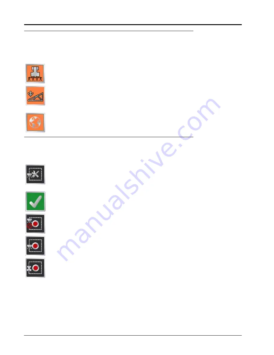
The Product Control Alarm icon is displayed if an alarm condition such as a low bin or tank, or
when product control cannot reach the target rate.
The AutoBoom Alarm icon is displayed if an alarm condition such as sensors too low or high, the
pressure is higher than the set point or if a sensor has gone off line. Refer to Chapter 10,
, for more information about the optional Glide Series AutoBoom system and
troubleshooting AutoBoom alarms.
Touch the Show All Alarms icon to view all current alarm conditions.
AccuBoom™
The following tools and icons will be displayed when working in a job with the AccuBoom feature enabled.
Select the zone mapping tools to display AccuBoom and zone map tools available for the current
job. Tools displayed in this menu may only appear if certain map features are present within the
current job. Read the descriptions of the following tools for more information regarding when the
tool or feature is available.
While editing zone maps, the Home button is replaced with the Accept button. To save the
currently displayed map and restore normal Menu tools, select the Accept button.
Touch the Record No-Spray Zone icon to begin recording points along a no-spray zone boundary.
The area inside of the completed boundary will become a no-spray zone.
Touch the Record Spray Zone icon to begin recording points along a spray zone boundary. The
area inside of the completed boundary will become a spray zone.
Touch the Record Field Boundary icon to create a new AccuBoom field boundary. With zone
mapping mode enabled, AccuBoom will assign a minimum of three boom widths outside of the
completed boundary as a no-spray zone.
Содержание Envizio Pro
Страница 3: ......
Страница 13: ...Table of Contents x Envizio Pro and Envizio Pro II Installation and Operation Manual ...
Страница 32: ...3 P N 016 0171 493 Rev I 17 Installation FIGURE 1 Envizio Pro Kit Contents Drawing Number 054 2040 004 ...
Страница 51: ...Chapter 4 36 Envizio Pro and Envizio Pro II Installation and Operation Manual ...
Страница 65: ...Chapter 5 50 Envizio Pro and Envizio Pro II Installation and Operation Manual ...
Страница 193: ...Chapter 9 178 Envizio Pro and Envizio Pro II Installation and Operation Manual ...
Страница 197: ...Chapter 10 182 Envizio Pro and Envizio Pro II Installation and Operation Manual ...
Страница 229: ...Appendix D 214 Envizio Pro and Envizio Pro II Installation and Operation Manual ...
Страница 285: ...Index 270 Envizio Pro and Envizio Pro II Installation and Operation Manual ...


