Appendix K
256
Envizio Pro™ and Envizio Pro II® Installation and Operation Manual
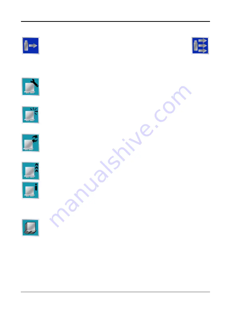
Transfer To Field Computer
Select the left icon to transfer a selected file to the field computer or the right icon to
transfer all files of the selected type currently stored on the USB flash drive.
CAN Diagnostics
Touch this icon to readdress product control nodes connected to the CANbus. Readdressing
product control nodes may be necessary if a node is not detected by the field computer. Verify that
the node is properly powered and connected to the CANbus communication lines before
readdressing the product control nodes. See the
for more information.
Select this icon to reset all product control nodes to their default values. Use the
section on page vii if necessary to record the required calibration values for
system operation. To help record additional settings for each node, step through or review the
section on page 44. After resetting nodes, it is recommended to run
the Product Control Setup Wizard to reconfigure each product node or control channel.
Touch this icon to retry CAN communications. If a node is not recognized when starting up the field
computer, restarting CAN communication may allow the system to recognize the node without
further troubleshooting steps. If a node is still not detected, additional troubleshooting or
readdressing the CANbus may be required. Refer to the
section on page 31 for additional information.
Touch this icon to update CAN nodes via the field computer. Review Appendix E,
, for more information on obtaining node update files and performing an
update via the field computer.
Detailed node hardware information is available by selecting a node listed on the CAN Diagnostics
screen and touching this icon. The hardware summary screen provides node operating
information that may be helpful when contacting technical support or while troubleshooting CAN
communication issues.
Note:
If the node is not capable of providing hardware information, the Hardware Summary screen will
display “N/A” for the unavailable diagnostic values.
The Raven product controller node is capable of providing up to four product control channels on
an Envizio Pro control system. By default, the product controller will make two control channels
available to the field computer for controlling product application.
Select one of the product controller node channels and select the Select Channels icon (shown to
the left) to set the number of control channels available via the node.
Note:
The Select Channels icon will display the current number of channels which the node is providing
to the field computer. Each control channel must be configured separately via the Tools Menu.
Содержание Envizio Pro
Страница 3: ......
Страница 13: ...Table of Contents x Envizio Pro and Envizio Pro II Installation and Operation Manual ...
Страница 32: ...3 P N 016 0171 493 Rev I 17 Installation FIGURE 1 Envizio Pro Kit Contents Drawing Number 054 2040 004 ...
Страница 51: ...Chapter 4 36 Envizio Pro and Envizio Pro II Installation and Operation Manual ...
Страница 65: ...Chapter 5 50 Envizio Pro and Envizio Pro II Installation and Operation Manual ...
Страница 193: ...Chapter 9 178 Envizio Pro and Envizio Pro II Installation and Operation Manual ...
Страница 197: ...Chapter 10 182 Envizio Pro and Envizio Pro II Installation and Operation Manual ...
Страница 229: ...Appendix D 214 Envizio Pro and Envizio Pro II Installation and Operation Manual ...
Страница 285: ...Index 270 Envizio Pro and Envizio Pro II Installation and Operation Manual ...


