Appendix K
260
Envizio Pro™ and Envizio Pro II® Installation and Operation Manual
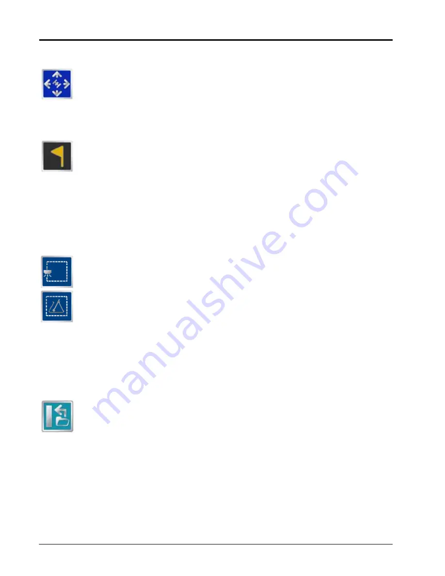
Drift Shift
The drift shift feature allows the operator to manually adjust, or nudge, the reported GPS position
of all features (e.g. boundaries, coverage and zone maps, field markers, and guidance lines, etc.)
within the job simultaneously. This feature allows the operator to manually correct for GPS drift
over the course of a field operation or to “recalibrate” the position of field features if the job is
resumed at a later date or time.
Field Markers
Field markers allow the operator to mark locations such as well heads, rock piles, or points of
interest during a field operation. Markers will be displayed during the operation and will allow the
operator to view the marker information.
Toggle Maps on the Guidance Screen
During a job with an active prescription or zone map, the field computer will display either map on the
Guidance and Field Review screens. If both a prescription map and a zone map will be used, the operator may
toggle which map to display on the guidance and field review screens by selecting the toggle maps icon.
To toggle the displayed map, touch:
The view zone map icon to view the loaded zone map.
The view prescription map icon to display the loaded prescription map on all guidance displays.
A-B Path Tools
The following tools and features may be found in the Menu when the Straight Line, Fixed Contour or Pivot
guidance patterns are active.
Loading an A-B Line
If an A-B Line has been saved on the field computer, touch the Load A-B Line icon to load a saved
line into the current job. This icon will not appear if an A-B Line has already been set. Reset the
line to access the Load A-B Line tool.
Note:
The A-B Line must be stored in the field computer internal memory to be able to access and load
the guidance path. Be sure to transfer all necessary files to the field computer before beginning a
job.
A-B Lines stored on the field computer cannot begin with a space.
Содержание Envizio Pro
Страница 3: ......
Страница 13: ...Table of Contents x Envizio Pro and Envizio Pro II Installation and Operation Manual ...
Страница 32: ...3 P N 016 0171 493 Rev I 17 Installation FIGURE 1 Envizio Pro Kit Contents Drawing Number 054 2040 004 ...
Страница 51: ...Chapter 4 36 Envizio Pro and Envizio Pro II Installation and Operation Manual ...
Страница 65: ...Chapter 5 50 Envizio Pro and Envizio Pro II Installation and Operation Manual ...
Страница 193: ...Chapter 9 178 Envizio Pro and Envizio Pro II Installation and Operation Manual ...
Страница 197: ...Chapter 10 182 Envizio Pro and Envizio Pro II Installation and Operation Manual ...
Страница 229: ...Appendix D 214 Envizio Pro and Envizio Pro II Installation and Operation Manual ...
Страница 285: ...Index 270 Envizio Pro and Envizio Pro II Installation and Operation Manual ...


