P/N 016-0171-493 Rev. I
261
Reference of Icons
Setting A-B Points
To create a New A-B Line, the operator must set A and B
points. The following icons and tools may be used to set
a New A-B Line.
Touching the Set A icon will place the first, or A, point of
the path at the vehicle’s current location. Regardless of
where the vehicle moves from this point, the field
computer will use the selected pattern to connect this
point with the next set point. After the Set A icon is selected, the Set B icon will appear.
Touch the Set B icon to place the second, or B, point of the guidance path. Once the B point has been set, the
field computer will use the selected Pattern to create the Guidance Path displayed on the Guidance screen.
Set B by Heading
The Set B by Heading feature is only available with the Straight Line Guidance Pattern. This feature allows the
operator to set an A-B Line before completing the first swath.
Use the Set B by Heading feature to create a guidance path along a heading. Touch this icon and
use the displayed keypad to enter a heading between 0° and 359° (with 0° being due North).
A-B Path Configuration
The following tools are available in the Menu when a compatible A-B Line is displayed on the Guidance
screen.
Select the A-B Tools icon to access additional tools for use with the current A-B Line.
Select the Reset A-B Line icon to clear the displayed path. If the displayed path will need to be
recalled in the future, be sure to save the current path before selecting reset.
Touch the Save A-B Line icon to save the displayed path. Once saved, an A-B Line can be
recalled at any time or loaded into other jobs. In addition, saved paths can be transferred from the
field computer via the File Maintenance feature. See Chapter 8,
, for details on the File Maintenance feature and transferring saved paths.
Use the Re-calibrate A-B Line tool to re-calibrate the displayed path to the machine’s current
position. Due to DGPS drift over time, this feature allows the operator to re-calibrate the A-B Line
to a known position in a field.
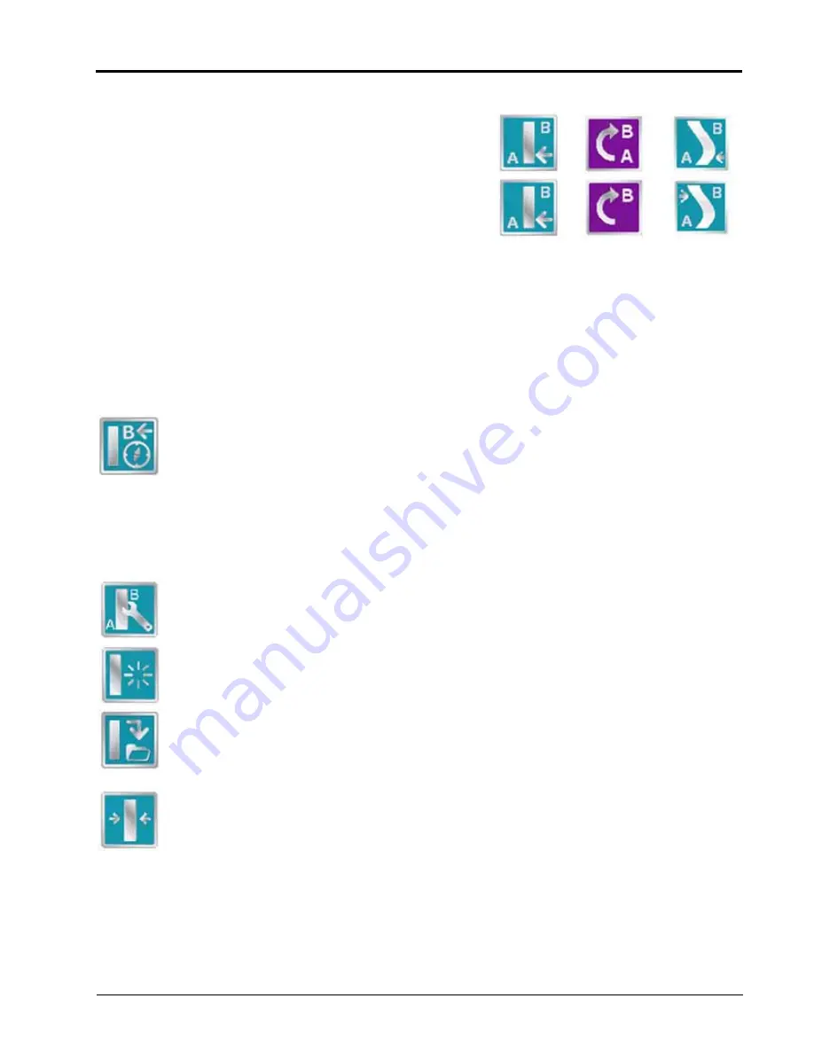
Straight (A-B) Line
Pivot
Fixed Contour
Set A
Set B
Содержание Envizio Pro
Страница 3: ......
Страница 13: ...Table of Contents x Envizio Pro and Envizio Pro II Installation and Operation Manual ...
Страница 32: ...3 P N 016 0171 493 Rev I 17 Installation FIGURE 1 Envizio Pro Kit Contents Drawing Number 054 2040 004 ...
Страница 51: ...Chapter 4 36 Envizio Pro and Envizio Pro II Installation and Operation Manual ...
Страница 65: ...Chapter 5 50 Envizio Pro and Envizio Pro II Installation and Operation Manual ...
Страница 193: ...Chapter 9 178 Envizio Pro and Envizio Pro II Installation and Operation Manual ...
Страница 197: ...Chapter 10 182 Envizio Pro and Envizio Pro II Installation and Operation Manual ...
Страница 229: ...Appendix D 214 Envizio Pro and Envizio Pro II Installation and Operation Manual ...
Страница 285: ...Index 270 Envizio Pro and Envizio Pro II Installation and Operation Manual ...


