Chapter 2. Signal Descriptions and Clocking
2-21
Detailed Signal Descriptions
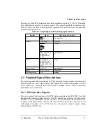
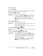
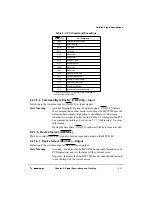
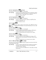
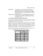
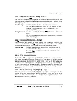
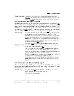
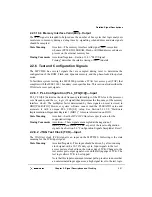
2.2.2.10.2 Data Parity (PAR[0:7])—Input
Following are the state meaning and timing comments for PAR[0:7] as input signals.
State Meaning
Asserted/Negated—Represents the byte parity or ECC bits being
read from memory (PAR0 is the most-significant parity bit and
corresponds to byte lane 0 which is selected by CAS0 or DQM0).
Timing Comments
Assertion/Negation—PAR[0:7] are valid concurrent with
MDH[0:31] and MDL[0:31].
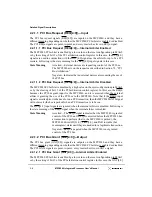
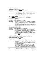
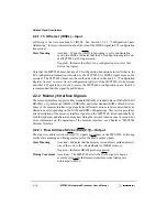
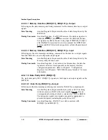
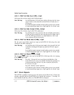
2.2.2.11 ROM Address 19:12 (AR[19:12])—Output
The ROM address 19–12 (AR[19:12]) signals are output signals only for the ROM address
function. Note that these signals are both input and output signals for the memory parity
function (PAR[0:7]). Following are the state meaning and timing comments for AR[19:12]
as output signals.
State Meaning
Asserted/Negated—Represents bits 19–12 of the ROM/Flash
address. The other ROM address bits are provided by AR[10:0] as
shown in Section 6.4.1, “ROM/Flash Address Multiplexing.”
Timing Comments
Assertion/Negation—The ROM address is valid on assertion of
RCS0 or RCS1.
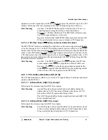
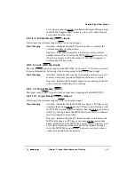
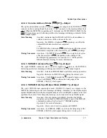
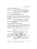
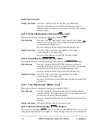
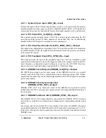
2.2.2.12 SDRAM Clock Enable (CKE)—Output
The SDRAM clock enable (CKE) signal is an output on the MPC8240 (and is also used as
a reset configuration input signal). CKE is part of the SDRAM command encoding. See
Section 6.2, “SDRAM Interface Operation,” for more information. Following are the state
meaning and timing comments for the CKE output signal.
State Meaning
Asserted—Enables the internal clock circuit of the SDRAM memory
device.
Negated—Disables the internal clock circuit of the SDRAM
memory device.
Timing Comments
Assertion—CKE is valid on the rising edge of the
SDRAM_CLK[0:3] clock signals. See Section 6.2, “SDRAM
Interface Operation,” for more information.
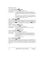
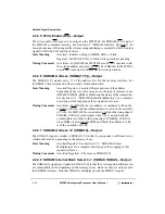
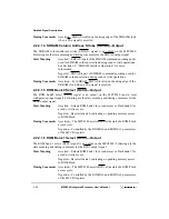
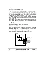
2.2.2.13 SDRAM Row Address Strobe (SDRAS)—Output
The SDRAM row address strobe (SDRAS) signal is an output on the MPC8240. Following
are the state meaning and timing comments for the SDRAS output signal.
State Meaning
Asserted/Negated—SDRAS is part of the SDRAM command
encoding and is used for SDRAM bank selection during read or write
operations. See Section 6.2, “SDRAM Interface Operation,” for
more information.
Содержание MPC8240
Страница 1: ...MPC8240UM D Rev 1 1 2001 MPC8240 Integrated Processor User s Manual ...
Страница 38: ...xviii MPC8240 Integrated Processor User s Manual TABLES Table Number Title Page Number ...
Страница 48: ...xlviii MPC8240 Integrated Processor User s Manual Acronyms and Abbreviations ...
Страница 312: ...6 94 MPC8240 Integrated Processor User s Manual ROM Flash Interface Operation ...
Страница 348: ...7 36 MPC8240 Integrated Processor User s Manual PCI Host and Agent Modes ...
Страница 372: ...8 24 MPC8240 Integrated Processor User s Manual DMA Register Descriptions ...
Страница 394: ...9 22 MPC8240 Integrated Processor User s Manual I2O Interface ...
Страница 412: ...10 18 MPC8240 Integrated Processor User s Manual Programming Guidelines ...
Страница 454: ...12 14 MPC8240 Integrated Processor User s Manual Internal Arbitration ...
Страница 466: ...13 12 MPC8240 Integrated Processor User s Manual Exception Latencies ...
Страница 516: ...16 14 Watchpoint Trigger Applications ...
Страница 538: ...B 16 MPC8240 Integrated Processor User s Manual Setting the Endian Mode of Operation ...
Страница 546: ...C 8 MPC8240 Integrated Processor User s Manual ...
Страница 640: ...INDEX Index 16 MPC8240 Integrated Processor User s Manual ...

